
Related Manuals for Reliance HS 7000


Summary of Contents for Reliance HS 7000
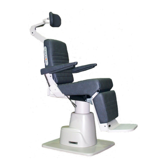
- Page 1 INSTALLATION AND OPERATING INSTRUCTIONS OWNERS MANUAL MODEL 7000 LOW VOLTAGE CONTROL CHAIR Premiere Designer SERIES and COLLECTION Models...
- Page 2 QUALITY MANAGEMENT SYSTEM REGISTERED TO ISO 13485 M A D E I N AM E R I C A Reliance® Medical Products, Inc. • 3535 Kings Mills Road • Mason, Ohio 45040-2303 • 1-800-735-0357 • www.reliance-medical.com...
-
Page 3: Table Of Contents
TABLE OF CONTENTSIMPORTANT INFORMATION..........4 4. PROGRAMMING THE CHAIR........13 4.1. Safety/Shutdown Feature......13 1. INTRODUCTION............5 To ENTER Safety/Shutdown Mode......13 TECHNICAL SPECIFICATIONS.........6 To EXIT Safety/Shutdown Mode......13 2. INSTALLATION............7 4.2. Individual Programming of the RAISE TOP, RECLINE TOP, RAISE BASE, and LOWER BASE switch located on the 2.1. -
Page 4: Information
IMPORTANT INFORMATION Alternating Current-AC SAFETY SYMBOLS Safe Working Load “DANGER”, “WARNING”, or “CAUTION” The exclamation point within an equilateral triangle is intended to alert the user to the presence of important operating and maintenance (servicing) instructions in this “Attention, Consult Accompanying Installation and Operating Instructions. -
Page 5: Introduction
T H E D A N G E R S Y M B O L you have any questions concerning the use and care IDENTIFIES SPECIAL INSTRUCTIONS OR of any Reliance® product, contact the Reliance® PROCEDURES WHICH, IF NOT CORRECTLY FOLLOWED, COULD RESULT IN LOSS OF Distributor, where you purchased this product or contact LIFE OR PERSONAL INJURY. -
Page 6: Technical Specifications
IMPORTANT USER WARNINGS WARNING: TO PREVENT FIRE OR ELECTRICAL SHOCK HAZARD, DO NOT EXPOSE THIS EQUIPMENT TO RAIN OR MOISTURE. WARNING: EXPLOSION HAZARD. THIS EQUIP- MENT MUST NOT BE USED IN THE PRESENCE AVERTISSEMENT : POUR ÉVITER UN OF FLAMMABLE ANESTHETICS. I N C E N D I E O U U N R I S Q U E D E C H O C É... -
Page 7: Installation
REMARQUE : Si cette chaise est achetée avec both base clamping boards. un support à instruments Reliance®, le câble de commande de la chaise fourni permettra un fonctionnement adéquat. Se référer au manuel du 2.1.1.2. It is recommended that the skid be positioned as support d’instrument pour savoir comment faire la... -
Page 8: Operation
3. OPERATION REMARQUE : Les interrupteurs RAISE (LEVER) et LOWER (BAISSER) la base sur le dossier de la chaise sont programmables. Selon la conception CAUTION: Caution should be taken to ensure initiale, le mouvement de la chaise S’ARRÊTE there are no obstructions (instruments, trays, lorsque l’un ou l’autre de ces interrupteurs est tables) impeding movement of the Chair. -
Page 9: Chair Top
REMARQUE NOTE: : Les interrupteurs RAISE (LEVER) et The RAISE and LOWER/RECLINE switches LOWER (BAISSER) la base sur l’interrupteur au pied on the Chair Back are programmable. By design, sont programmables. Selon la conception initiale, the motion of the Chair will CONTINUE when either le mouvement de la chaise S’ARRÊTE lorsque l’un of these switches is released. -
Page 10: Automatic Return
REMARQUE : Les interrupteurs RAISE (LEVER) CAUTION: This exam Chair is designed et LOWER (BAISSER/INCLINER) sur l’interrupteur for use with a patient properly positioned au pied sont programmables. Selon la conception in the Chair. Prior to reclining the Chair, initiale, le mouvement de la chaise S’ARRÊTE ensure that the patient is seated in the lorsque l’un ou l’autre de ces interrupteurs est Chair and that the patient position does... -
Page 11: Revolving/Rotation
Les interrupteurs à mémoire sur RECEIVES A IMPACT OR STRIKES AN OBJECT les côtés droit et gauche du dossier de la chaise WITH FORCE CONTACT RELIANCE® TECH fonctionnent indépendamment l’un de l’autre. Si SERVICE IMMEDIATELY. la fonctionnalité de mémoire est activée du côté... -
Page 12: Adjustment-No. 18, 22 Headrest
3.9.3. Adjustment-No. 18, 22 Headrest if it is not required. 3.9.3.1. There are three adjustments provided on the No. 3.9.5. Operation-No. 11, 21, 31 Headrest 18, 22 headrest. The first is the tension on the pad rotation. By tightening the two hex acorn nuts on the pad pivots with 3.9.5.1. -
Page 13: Adjustment C6 Headrest
three seconds while in Safety/Shutdown Mode. 3.9.8. C6 Headrest Adjustment 4.1.2 To EXIT Safety/Shutdown Mode, repeat the 3.9.8.1. The handle on the outermost knob can be above sequence. adjusted to any preferred, locked position. Simply push in on the large screw while pulling out on the 4.1.2.1 Depress and HOLD either STOP switch. -
Page 14: To Exit Setup Mode
4.2.3.4 Depress any of the following switches (including 4.3.3 A short beep (0.25 seconds) indicates NO BEEP footswitch), one at a time, to toggle its current setting - RAISE will occur when a switch is depressed. A long beep TOP, RECLINE TOP, RAISE BASE, OR LOWER BASE. When (1.05 seconds) indicates a BEEP occur when a switch is the switch is depressed, a SHORT beep (0.25 seconds) will depressed. -
Page 15: Home Feature
4.5. Home Feature NOTE: The Home Feature and Memory Feature can only be operated with the Base down and the Back 4.5.1 The Home Feature allows the user to program the fully upright See Section 3.5.2 Step 4 distance the chair lift will travel when starting from the fully lowered position. - Page 16 5.1.2. To remove fuses from fuse drawer, tilt fuses in direction of arrows as shown in Figure 6. Examine the fuses, replace as necessary. FIGURE 7 AC INPUT MODULE CAUTION : To avoid a bind of the Fuse Drawer within the AC Input Module, never install the Fuse Drawer into the AC Input Module without fuses.
-
Page 17: Troubleshooting Guide
TROUBLESHOOTING GUIDE PROBLEM PROBLEM CAUSE SOLUTION CHAIR WILL NOT OPERATE. 1) POWER CORD NOT PLUGGED IN. 1) CHECK ALL WIRING CONNECTIONS. 2) NO AC POWER AT WALL RECEPTACLE. 2) RESTORE OUTLET POWER. 3) BLOWN LINE FUSE. 3) REPLACE FUSE. OUTLET POWER OK, BUT NO 1) BLOWN LINE FUSE. -
Page 18: Cleaning And Maintenance
CLEANING AND MAINTENANCE Cleaning the Upholstery PRÉCAUTION: Ces solvants sont extrêmement When cleaning upholstery, it is suggested that you use all inflammables. Faites très attention lors du recommended commercial cleaning agents in an inconspicu- nettoyage et avisez le personnel dans la ous spot to check for potential damage to the upholstery zone de tout danger. - Page 19 NOTES IN-7000...
-
Page 20: Parts List
Should your Exam Chair not perform properly, or if replacement parts are need, contact the Reliance® Distributor, where you purchased this product or contact the Technical Service Department, Reliance® Medical Products, Inc., 3535 Kings Mills Road, Mason, Ohio 45040-2303, or call (800) 735-0358. -
Page 21: Model 7000 Chair Assembly
FIGURE 8 7000 CHAIR ASSEMBLY (DESIGNER) ADJUSTABLE 6"-20" 8, 9 MODEL AND SERIAL 40.25"±.25 HIGH BASE NUMBER PLATE 37.75"±.25 LOW BASE AT LOWEST POSITION SEAT HEIGHT (MIN.) HIGH BASE-22 3/4" (10 5/8" TRAVEL) LIFT LOW BASE-20 1/4" (8 1/2" TRAVEL) 2"... -
Page 22: Model 7000 Chair Assembly (Premiere)
FIGURE 9 7000 CHAIR ASSEMBLY (PREMIERE) ADJUSTABLE 6"-20" 8, 9 MODEL AND SERIAL 40.25"±.25 HIGH BASE NUMBER PLATE 37.75"±.25 LOW BASE AT LOWEST POSITION SEAT HEIGHT (MIN.) HIGH BASE-22 3/4" (10 5/8" TRAVEL) LIFT LOW BASE-20 1/4" (8 1/2" TRAVEL) 2"... -
Page 23: Chair Top Assembly
FIGURE 10 7000 CHAIR ASSEMBLY 74, 77 61,62 2, 62 Premiere Only 74, 76 Premiere Only 72 (2) 73, 79 Per Side 55, 59 61, 62 78, 79 (2) Per Side Premiere Only Premiere Only 55, 59 3, 57 31 32 16 28 29 16 27 2, 62... - Page 24 PART NO. DESCRIPTION ITEM PART NO. DESCRIPTION ITEM 1546699 Hinge Cable Assembly 0732699 1/2 Retaining Ring 0708499 H.H.C.S. 3/8-16 x 1-1/4 6 Circuit Plug 164389 0728299 1/4 Split Lock Washer Apron Board Assembly 1422492 0713199 R.H.M.S. 1/4-20 x .75 0722899 S.S.H.S.
- Page 25 ITEM PART NO. DESCRIPTION ITEM PART NO. DESCRIPTION 546299 Ribb on Cable 0606399 #8-32 Hinge Brac ket Pin 387303 Plug Button* Apron Link 0603685 603399 Trua rc Ring Back Bracket - Right* 0125372 126485 Apro n Bracket 0125472 Back Bracket - Left* 660899 6 Cir cuit Cap...
-
Page 26: Chair Base Assembly
FIGURE 11 CHAIR BASE ASSEMBLY 3, 4 30, 17 30, 17 16, 17 41, 40 IN-7000... - Page 27 ITEM PART NO. DESCRIPTION ITEM PART NO. DESCRIPTION 1127599 Union Tee 2081203 Base 2065599 Base Cover 1659299 Power Cord Assembly 120V (US) 2065199 Base Housing - Low - RH 2832299 Power Cord Assembly 230V (US) 2065399 Base Housing - High - RH 2363100 Power Cord Assembly INT’L Options 2065299...
-
Page 28: Lift Assembly
FIGURE 12 LIFT ASSEMBLY 33 & 37 IN-7000... - Page 29 ITEM PART NO. DESCRIPTION ITEM PART NO. DESCRIPTION 1012795 Lift Base 0733299 Retaining Ring 1019095 Lift Top 0512599 Backup Ring 0439979 Switch Plate 0730899 U - Pack 0929699 Insulator 0512499 Piston Ring 1011399 Switch 0353199 Cylinder Gasket 0727599 Drive Screw 0569299 Pin - Roll 0731499...
-
Page 30: Headrest Assembly
FIGURE 13 # 11 HEADREST ASSEMBLY 16, 17 10, 17 ITEM PART NO. DESCRIPTION 1557573 Uph # 11 Pad Assembly** 1558897 Headrest Cover 1562499 3/8" Adjustable Handle 1558903 Mounting Plate* 1559295 Headrest Lock Block 1559395 Headrest Pad Mounting Plate 1207199 3/4 O.D x 3/8 I.D x 3/4 Spacer 1562899 S.H.S.S. -
Page 31: Headrest Assembly
FIGURE 14 # 10 HEADREST ASSEMBLY ITEM PART NO. DESCRIPTION 0665073 Uph # 10 Board Assembly** 0574173 Pillow Assembly - #10** 0567903 High Back Cover* 0568003 Pillow Back Cover* 0845199 F.H.W.S. #6 x .50 - Phil 0569699 O.H.W.S. #6 x 3/4 0569799 #6 Finishing Washer 0557499... -
Page 32: Headrest Assembly
FIGURE 15 # 18 & # 22 HEADREST ASSEMBLY IN-7000... - Page 33 ITEM PART NO. DESCRIPTION 0475673 Pad Assembly - No. 18* 1680073 Pad Assembly - No. 22* 1460492 Yoke Assembly* 1460592 Gear & Bracket Assembly* 1470692 Actuator & Lock Gear Assembly 1425299 Pivot Cap, Right 1425399 Pivot Cap, Left 0307599 Screw, Shoulder 1/4 x 1 0726099 S.H.S.S.
-
Page 34: Headrest Assembly
FIGURE 16 # 21 HEADREST ASSEMBLY 16, 20 10, 20 IN-7000... - Page 35 ITEM PART NO. DESCRIPTION 1846373 Uph. #21 Board Assembly** 1558897 Headrest Cover 0574173 Pillow Assembly** 0568003 Pillow Board Back Cover* 1558903 Mounting Plate* 1562499 3/8” Adjustable Handle 1559395 Headrest Pad Mounting Plate 1559295 Headrest Lock Block 0472999 Retaining Ring 1559599 R.H.M.S., 1/4-20 x 2 1/2 1526399 T.H.M.S., 5/16-18 x 1/2...
-
Page 36: C6 Headrest Assembly
FIGURE 17 C6 HEADREST ASSEMBLY IN-7000... - Page 37 ITEM PART NO. DESCRIPTION 2262300 Uph. Pillow Artic Headrest** 1948600 Back Cover Assembly 2257799 Pin, Elevator Bar 2257699 Pin, Pivot 2262199 U-Bracket, Lock Hinge 2287299 Roll Pin, .13 x 1.25 2261999 S.H.C.S., #10-24 x .50 Long 0527699 Washer, 1.13 O.D x .76 I.D. 2336000 Sub-Assembly, Lock Mechanism Elevator Bar, Short Bend...
-
Page 38: Headrest Assembly
FIGURE 18 # 30 HEADREST ASSEMBLY IN-7000... - Page 39 ITEM PART NO. DESCRIPTION 1920873 Uph. Pillow - Magnetic** 1920973 Pillow Back Cover Assembly** 3036573 Uph. Headrest Board** 0567903 Headrest Back Cover* O.H.W.S. #6 x 3/4 0569699 0569799 #6 Finishing Washer 0557499 Mounting Plate Assembly 0123203 Bracket Cover* 1111399 F.H.C.S 1/4-20 x 3/4 - Socket 0788699 S.H.C.S.
-
Page 40: Headrest Assembly
FIGURE 19 # 31 HEADREST ASSEMBLY 10, 19 IN-7000... - Page 41 ITEM PART NO. DESCRIPTION 1920873 Uph. Pillow - Magnetic 1920973 Pillow Back Cover Assembly 3075173 Uph. Headrest Board - #31 1558897 Headrest Cover 1558903 Mounting Plate* 1562499 3/8” Adjustable Handle 1559395 Headrest Pad Mounting Plate 1559295 Headrest Lock Block 0472999 Retaining Ring 1559599 R.H.M.S., 1/4-20 x 2 1/2...
-
Page 42: Wiring Diagram - 7000
FIGURE 20 WIRING DIAGRAM IN-7000... - Page 43 IN-7000...
- Page 44 NOTES IN-7000...
- Page 45 NOTES IN-7000...
- Page 46 NOTES IN-7000...
-
Page 47: Limited Warranty
LIMITED WARRANTY The Reliance® product must be used only for the purposes and in the manner described in the literature distributed with the product. The products are warranted against defective materials and workmanship for a period of one (1) year from date of installation. Products or parts thereof will be repaired or replaced as required at Reliance®... - Page 48 MADE IN AMERICA Reliance Medical Products 3535 Kings Mills Road Authorized European Community Representative Mason, Ohio 45040-2303 USA 1-800-735-0357(Customer Service) HAAG-STREIT UK 1-800-735-0358 (Technical Service) Edinburgh Way (513) 398-3937 Http://www.reliance-medical.com Harlow, Essex, England CM20 2TT P/N 27178 REV G United Kingdom ©...
Need help?
Do you have a question about the HS 7000 and is the answer not in the manual?
Questions and answers