
Related Manuals for Reliance 7900


Summary of Contents for Reliance 7900
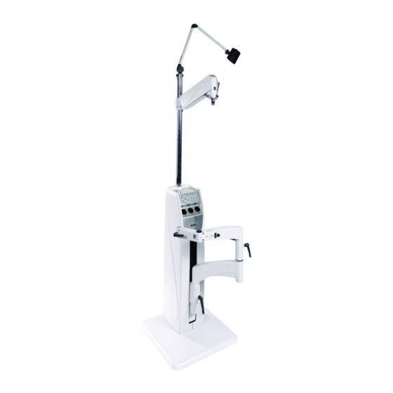
- Page 1 EN FR INSTALLATION AND OPERATING INSTRUCTIONS OWNERS MANUAL MODEL 7900 OPHTHALMIC INSTRUMENT STAND...
- Page 2 SERIAL NUMBER For your future reference, mark the serial number in the space provided. QUALITY MANAGEMENT SYSTEM REGISTERED TO ISO 13485 MADE IN AMERICA Reliance® Medical Products, Inc. • 3535 Kings Mills Road • Mason, Ohio 45040-2303 • 1-800-735-0357 • www.reliance-medical.com...
-
Page 3: Table Of Contents
2.6 Refractor Arm - Dual Lock......11 Control System...........28 2.7 Overhead Lamp..........11 CLEANING AND MAINTENANCE .....29 2.8 Final Assembly...........11 PARTS LIST.............30 2.8.1 Console/Base Cap........11 Model 7900 Instrument Stand Assembly....31 2.9 Slit Lamp Arm........11 Base Assembly..........32 2.10 Chair Assembly..........12 Roller Frame Assembly........34 2.11 Miscellaneous..........13 Outlet Plate Assembly.........36 3. -
Page 4: Important Information
-30 to +60º C Relative Humidity: Operating: 5%RH to 95%RH « REMARQUE » : Remarque indique des points without condensation d’intérêt particulier ou des renseignements Storage: 10%RH to 100%RH, additionnels. including condensation Atmospheric Pressure: Operating: 700hPa - 1060hPa Storage: 500hPa - 1060hPa IN-7900... -
Page 5: Introduction
UNE BLESSURE OU UN DOMMAGE À L’ÉQUIPEMENT, SEULS LES DISTRIBUTEURS 1.1. This Installation and Operating Instruction contains RELIANCE® AUTORISÉS DEVRAIENT information applicable only to the Reliance® Model 7900 INSTALLER OU DÉPLACER L’ÉQUIPEMENT. Ophthalmic Instrument Stand also known as Floor Unit. 1.2. -
Page 6: Technical Specifications
PRESENCE OF FLAMMABLE ANESTHETICS. This equipment is rated Class I, Type B AVERTISSEMENT : RISQUE D’EXPLOSION. CET ÉQUIPEMENT NE DOIT PAS ÊTRE Equipment Model UTILISÉ EN PRÉSENCE D’ANESTHÉSIQUES Instrument Stand 7900 INFLAMMABLES Volts Hertz Amps 120V 50/60 10.0 POTENTIAL ELECTROMAGNETIC or OTHER... -
Page 7: Installation
G R O U P T H R E E I N S T R U M E N T A R M S TOGETHER ON ONE SIDE OF THE STAND. DISTRIBUTE INSTRUMENT WEIGHT AS EQUALLY AS PRACTICAL. AVOID FAST OR FORCEFUL MOVEMENT OF INSTRUMENT ARMS. IN-7900... - Page 8 Slit Lamp Arm from Roller Frame Chair Control Aux from Back from Outlet Cover Plate Mounting Tabs Overhead Lamp Ground from AC Input Switchpack (SW1) Ground from 3rd Arm & Slit Optional Lamp Chair Control Switchpack FIGURE 2 (SW2) FIGURE 2 IN-7900...
-
Page 9: Support Column Installation
Tighten the set screws under the Support Pin. Remove set screw from Installation Packet and install where shipping screw had been. Slide the Collar down firmly against the Console/Base Cap. Insert and tighten set screw. "3rd" ARM BINDING POSTS PROJECTOR FIGURE 3 IN-7900... -
Page 10: Third Arm
SIMILAIRE CONFORME AVEC IEC 60601- 1. UNE FOIS L’APPAREIL CONNECTÉ, LES To configure the Base Cap Beep-on-Switch Feature: COURANTS DE FUITE RÉSULTANTS DOIVENT ÊTRE CONFORMES À IEC 60601-1-1 POUR LES SYSTÈMES ÉLECTRIQUES MÉDICAUX. NE CONNECTEZ PAS DE DISPOSITIFS NON AUTORISÉS. IN-7900... -
Page 11: Refractor Arm - Dual Lock
Plates off of the Upper Arm. Loosen the center Screw holding the two plates together but do not completely remove it. Pull the two Plates apart and rotate them so the Outlet and Rocker Switch are now on the opposite side of the Upper Arm. IN-7900... -
Page 12: Chair Assembly
2.10. Chair Assembly 2.10.1 The chair control switches located on the Floor Unit may control any Reliance® low voltage chair. Refer to the chair’s Installation and Operatiing Instructions for unpacking and assembling the chair. 2.10.2. A Chair Control Cable is provided to control the vertical movement of the Chair Base from the Floor Unit. -
Page 13: Miscellaneous
SITUÉE SUR L’ASSEMBLAGE DE PLAQUE DE COURANT EST CONÇUE POUR FOURNIR L’ALIMENTATION À UNE CHAISE D’EXAMEN SLIT LAMP DE PATIENT RELIANCE® OU À UN DISPOSITIF TABLE MÉDICAL SIMILAIRE CONFORME À IEC 60601-1. UNE FOIS L’APPAREIL CONNECTÉ, LES COURANTS DE FUITE RÉSULTANTS DOIVENT ÊTRE CONFORMES À... -
Page 14: Third Arm
Outer Arm controls both vertical movement and the rotation of the Outer Arm. The small knob in the Outer Arm controls rotation of the Instrument at the outermost pivot point. 3.2.2. Adjustment of the Spring counterbalance is as described in the Installation Instructions, Section 2.5.3. FIGURE 7 IN-7900... -
Page 15: Refractor Arm
Reliance®. Contactez each of which is adjustable. Tighten all three knobs with votre distributeur autorisé Reliance® ou Welch moderate hand pressure. This will allow you to move Allyn pour plus de détails. -
Page 16: Front Panel Controls
• The primary purpose of the switch is to turn the projector Instrument Wells when in the OFF position. ON and OFF. WARNING- MAIN POWER (120VAC OR 230VAC) IS ALWAYS PRESENT INSIDE THE SYSTEM WHEN THE POWER CORD IS PLUGGED INTO THE WALL. IN-7900... -
Page 17: Room Switch (Room)
Instructions. turned OFF. See Table 1. • See Switch 3 on Switchpack #1. • When enabled, turns power to the binding Posts (Indirect Ophthalmoscope) ON and OFF. • Turns the B/P LED ON when power is applied to the IN-7900... -
Page 18: Fuses
Diagrams at the end of this Manual. fusibles. PRÉCAUTION : Remplacez le(s) fusible(s) comme indiqué. Tous les fusibles doivent être remplacés par un fusible de la même dimension et de la même valeur. Se référer aux schémas de câblage à la fin de ce IN-7900 manuel. -
Page 19: Control System
• cause unintended operation of the room Turn Switch 3 ON to enable Well #2 to affect room lights. lights when room lights are controlled by • Turn Switch 3 OFF to disable Well #2 from affecting room lights. IN-7900... -
Page 20: Entering And Exiting Programming Mode
(The Base Cap Circuit Board does not contain Dip simultaneously for 3 seconds. The info screen will go to Switches.) Scene 1. The Base Cap controls just two IR functions: 3.8.3.6. Navigating Menus in Programming Mode • the Room Lights Switch on the Slit Lamp Arm, and IN-7900... - Page 21 To assign the Pico wireless control as a zone 4. Use the zone raise/lower buttons to choose the non controller, use the Master buttons to select “Zone” and IN-7900 press the OK button to accept. Use the zone raise/...
- Page 22 YOUR IR RECEIVER MUST BE RHEOSTAT INSTALLED BY A QUALIFIED ELECTRICIAN IN ACCORDANCE WITH ALL APPLICABLE REGULATIONS. IMPROPER WIRING CAN RESULT IN PERSONAL INJURY OR DAMAGE TO YOUR IR RECEIVER OR OTHER EQUIPMENT. FIGURE 16 AVERTISSEMENT : VOTRE RÉCEPTEUR IF INDIRECT HANGER SWITCH IN-7900...
- Page 23 800 WATTS/VA PER ZONE (120V) 1200 WATTS/VA PER ZONE (220-240V) LOAD TYPES: INCANDESCENT FLUORESCENT (DIM OR NON-DIM) REQUIRES RELIANCE P/N 29737 FLUOR. DIMMING BALLAST INTERFACE, 220-240V FLUORESCENT POWER MODULE 120-277V, 120V ONLY RELIANCE P/N 29736 OR LED INTERFACE, 10V 100-277V...
- Page 24 FIGURE 19 FLUORESCENT INTERFACE P/N 17187 IN-7900...
- Page 25 (4 Gang US Backbox by Others) FIGURE 21 Installation Diagram: Three Zone Fluorescent ON/OFF 120 VAC or 277 VAC Note: See the Installer’s Guide that came with your IR Receiver. REMARQUE : Consultez le guide de l’installateur fourni avec votre récepteur IR. IN-7900...
- Page 26 120 - 127 V 1-6: Dimmed/Switched line voltage outputs 220 - 240 V 12 AWG (4.0 mm ) Distribution each terminal Panel Incandescent load Load controlled by power module or interface Power module or interface FIGURE 22 INSTALLATION DIAGRAM-THREE ZONE IN-7900...
-
Page 27: Troubleshooting Guide
RECEIVING POWER INTO BASE CAP OR CONSOLE BASE CAP OR CONSOLE Should your Instrument Stand not perform properly, contact the Reliance® Distributor, where you purchased this product or contact the Technical Service Department, Reliance® Medical Products, Inc., 3535 Kings Mills Road, Mason, Ohio 45040-2303, or call (800) 735-0358. -
Page 28: Control System
ARM AGAIN LIGHTS 3) ROOM LIGHTS DO NOT A) RECEIVER NOT PROGRAMMED A) REPROGRAM RECEIVER RESPOND AS DESIRED CORRECTLY 4) WALL UNIT DOES NOT A) CHECK WIRING A) CONTACT INSTALLER OF RECEIVER AFFECT LIGHTS B) CHECK RECEIVER B) EXCHANGE RECEIVER IN-7900... -
Page 29: Cleaning And Maintenance
Note: Equipment should be cleaned as needed or per local or healthcare profession guidelines. REMARQUE : L’équipement devrait être nettoyé au besoin ou selon les directives locales ou celles des professions de la santé. IN-7900... -
Page 30: Parts List
Should your Instrument Stand not perform properly, or if replacement parts are needed, contact the Reliance® Distributor, where you purchased this product or contact the Technical Service Department, Reliance® Medical Products, Inc., 3535 Kings Mills Road, Mason, Ohio 45040-2303, or call (800) 735-0358. -
Page 31: Model 7900 Instrument Stand Assembly
FIGURE 23 MODEL 7900 INSTRUMENT STAND ASSEMBLY MODEL AND SERIAL NUMBER PLATE ITEM PART NO. DESCRIPTION ITEM PART NO. DESCRIPTION Base Assembly* (See Figure 24 ) 0514780 Collar-Chrome Slit Lamp Arm Assembly* (See Figure 28) 0722699 Sckt. H.S.S. 1/4 x 1/4... -
Page 32: Base Assembly
FIGURE 24 BASE ASSEMBLY IN-7900... - Page 33 Cable Clamp 2035099 THMS #10-32 x 3/8 0508599 3/8-16 Lock Nut 1282699 .625 Nylon Hole Plug To order complete Base Assembly use P/N’s. 1967692 7900 Base Assembly- 120V* 1967792 7900 Base Assembly- 230V* *Please specify paint color when ordering. IN-7900...
-
Page 34: Roller Frame Assembly
FIGURE 25 ROLLER FRAME ASSEMBLY To order complete Roller Frame Assembly use P/N. 1966192 7900 Roller Frame Assembly* *Please specify paint color when ordering. IN-7900... - Page 35 0729599 Washer - 3/8 1730599 12 Circuit Cap 0730199 Washer - 5/16 1225799 Lock Shoe Pin 0732599 Retaining Pin 0728399 Lockwasher - 5/16 Split 2725399 Upper Lockshoe 0506899 Snap Bushing 2725499 Lower Lockshoe 0506199 Ball Bearing 1730699 Wiring Clip IN-7900...
-
Page 36: Outlet Plate Assembly
FIGURE 26 OUTLET PLATE ASSEMBLY To order complete Outlet Plate Assembly use P/N’s. 1966992 Outlet Plate Assembly - 120V* 1967092 Outlet Plate Assembly - 230V* *Please specify paint color when ordering. IN-7900... - Page 37 ITEM PART NO. DESCRIPTION 1969803 Outlet Plate-7900* 1082899 Receptacle, Single 15A/125V, NEMA 5-15R (120V) 1733499 Receptacle, Single 15A/250V, NEMA 6-15R (230V) 1976799 Power Entry Module W/Filter Fusedrawer, 2 Pole (in Item 3) 1682399 Fuse, 10A/250V (120V) 1634299 Fuse, 6.3A/250V (230 V) 0290299 T.H.M.S.
-
Page 38: Back Cover Assembly
To order complete Back Cover Assembly use P/N’s. 1967192 Back Cover Assembly - 120V* 1967292 Back Cover Assembly - 230V* 2047792 Back Cover Assembly - Base Cap - 120V* 2047892 Back Cover Assembly - Base Cap - 230V* *Please specify paint color when ordering. IN-7900... - Page 39 ITEM PART NO. DESCRIPTION 1971403 Back Cover-7900* 2034692 Auxiliary Cable Assembly - Console - 120V 2034792 Auxiliary Cable Assembly - Console - 230V 2039992 Auxiliary Cable Assembly - Base Cap - 120V 2040092 Auxiliary Cable Assembly - Base Cap - 230V...
-
Page 40: Slit Lamp Arm Assembly
FIGURE 28 SLIT LAMP ARM ASSEMBLY IN-7900... - Page 41 To order complete Slit Lamp Arm Assembly use P/N’s. 1965792 Slit Lamp Arm Assembly- W/O IR 1965892 Slit Lamp Arm Assembly- W/ IR 1965992 Slit Lamp Arm Assembly W.C.-W/O IR 1966092 Slit Lamp Arm Assembly W.C..-W/ IR *Please specify paint color when ordering. IN-7900...
-
Page 42: Model 5250 Dual Lock Refractor Assembly
FIGURE 29 MODEL 5250 DUAL LOCK REFRACTOR ASSEMBLY SERIAL LABEL IN-7900... - Page 43 Label-Safe Working Load-20lbs To order complete Dual Lock Refractor Assembly use P/N’s. 525010 Refractor Suspension Arm Assembly - Standard (Dual Lock Refractor Arm) 525011 Refractor Suspension Arm Assembly - Wheelchair (Dual Lock Refractor Arm) *Please specify paint color when ordering. IN-7900...
-
Page 44: Model 5380 Auxiliary (3Rd) Arm Assembly
FIGURE 30 MODEL 5380 AUXILIARY (3RD) ASSEMBLY 32 (2) IN-7900... - Page 45 2074499 Label-Consult Accompanying Doc 0536599 Tension Spring 0728299 Washer - Split Lock 1/4 0536799 Wire Clip To order complete Auxiliary (3rd) Arm Assembly use P/N’s. 538011 Auxiliary (3rd) Arm Assembly - AC Plug* *Please specify paint color when ordering. IN-7900...
-
Page 46: Instrument Console Without Ir Assembly
FIGURE 31 INSTRUMENT CONSOLE MODULE ASSEMBLY W/O IR IN-7900... - Page 47 Spacer 1970399 Ribbon Cable Assembly 1979999 #10-32 x 1.5 P.H.M.S 1976899 Membrane Frame Assembly 2040292 B/P Jumper To order complete Console Assembly use P/N. 1968592 7900 Console Module Assembly Without IR *Please specify paint color when ordering. 31 9 IN-7900...
-
Page 48: Instrument Console With Ir Assembly
FIGURE 32 INSTRUMENT CONSOLE MODULE ASSEMBLY W/ IR IN-7900... - Page 49 #10-32 x 1.5 P.H.M.S 1976899 Membrane Frame Assembly 2040292 B/P Jumper 1976499 Face Plate - Mount Tab To order complete Console Assembly use P/N. 1968692 7900 Console Module Assembly With IR *Please specify paint color when ordering. 31 9 IN-7900...
-
Page 50: Base Cap With Ir Assembly
FIGURE 33 BASE CAP MODULE ASSEMBLY - WITH IR IN-7900... - Page 51 Face Plate - Mount Tab 1663092 Lamp Cord Jumper 1976899 Membrane Frame Assembly 1973592 Chair Control Jumper - Base Cap To order complete Console Assembly use P/N. 1968792 7900 Base Cap Module Assembly - with IR *Please specify paint color when ordering. IN-7900...
-
Page 52: Wire Diagram - Console (With And Without Ir)
FIGURE 34 WIRE DIAGRAM - CONSOLE (WITH AND WITHOUT IR) IN-7900... - Page 53 IN-7900...
-
Page 54: Wire Diagram Base Cap With Ir
FIGURE 35 WIRE DIAGRAM - BASE CAP - WITH IR IN-7900... - Page 55 IN-7900...
- Page 56 (NOTES) IN-7900...
- Page 57 (NOTES) IN-7900...
- Page 58 (NOTES) IN-7900...
-
Page 59: Limited Warranty
LIMITED WARRANTY The Reliance® product must be used only for the purposes and in the manner described in the literature distributed with the product. The products are warranted against defective materials and workmanship for a period of one (1) year from date of installation. Products or parts thereof will be repaired or replaced as required at Reliance®... - Page 60 MADE IN AMERICA Reliance Medical Products, Inc. 3535 Kings Mills Road Mason, Ohio 45040-2303 USA 1-800-735-0357 (Customer Service) 1-800-735-0358 (Technical Service) (513) 398-3937 Http://www.reliance-medical.com P/N 19700 REV K © Copyright 2009 Printed in U.S.A. Revised 8-2018-9065...
Need help?
Do you have a question about the 7900 and is the answer not in the manual?
Questions and answers