
Related Manuals for Neurosoft Neuron-Spectrum-1


Summary of Contents for Neurosoft Neuron-Spectrum-1
- Page 1 Technical Manual Neuron-Spectrum-1 Neuron-Spectrum-2 Neuron-Spectrum-3 Neuron-Spectrum-4 Neuron-Spectrum-4/P CloudEEG Digital Neurophysiological Systems TM015.03.002.000 (24.03.2020)
- Page 2 Electroencephalography (EEG) and long-latency Evoked Potential (EP). Polysomnography (PSG) derives from Electroencephalography (EEG) by the means of a dedicated software module and dedicated electrodes. The devices are portable and can register up to 8 (Neuron-Spectrum-1), 16 (Neuron-Spectrum-2), 19 (Neuron- Spectrum-3), 21 (Neuron-Spectrum-4, Neuron-Spectrum-4/P, CloudEEG) EEG channels, 1 (Neuron-Spectrum-1, Neuron-Spectrum-2, Neuron-Spectrum-3 and Neuron-Spectrum-4) or up to 4 polygraphic channels (Neuron- Spectrum-4/P, CloudEEG: ECG, EOG), 1 respiratory channel and 2 direct current channels (Neuron-Spectrum-4/P).
-
Page 3: Table Of Contents
Contents Introduction ....................... 4 Description and Operation ................5 1.1. Function ......................5 1.2. Safety Measures ................... 6 1.3. Specifications ....................6 1.4. Delivery Set ....................11 1.5. Technology and Operation ................17 1.6. Connectors and Indicators ................18 Installation ....................... 20 2.1. -
Page 4: Introduction
You can send your responses and recommendations to the following address: P.O. Box 10, Ivanovo, 153000, Russia or by e-mail: help@neurosoft.com You can find additional information on Neurosoft products on our website: www.neurosoft.com or ask questions by phone: +7 (4932) 59-21-12 (Service Center) -
Page 5: Description And Operation
Spectrum-4/P and intended for the recording of EEG and long-latency EP in any unshielded room. The devices are portable and can register up to 8 (Neuron-Spectrum-1), 16 (Neuron-Spectrum-2), 19 (Neuron-Spectrum-3), 21 (Neuron-Spectrum-4, Neuron- Spectrum-4/P, CloudEEG) EEG channels, 1 (Neuron-Spectrum-1, Neuron-... -
Page 6: Safety Measures
Neuron-Spectrum (Technical Manual) · Review, store and print of the recorded traces, results of their analysis and exam reports. A patient stimulation can be performed with the use of stimulators built in the device. The main condition for using the digital EEG systems is the good professional skills of the medical staff. - Page 7 Description and Operation Table 1. Continued Parameters Values Sensitivity 1–1000 µV/mm (step 1 µV/mm) Ratio error of sensitivity within ±5% Sweep speed at EEG recording 3–960 mm/s (step 1 mm/s) Sweep speed at EP recording 5, 10, 20, 50, 100, 200, 500 ms/div.
- Page 8 Neuron-Spectrum (Technical Manual) Table 1. Continued Parameters Values Direct Current Channels*** Number of channels Input range from –3 V up to +3 V Ratio error of voltage measurement in the range: · from 0.3 mV up to 1 mV within ±15% ·...
- Page 9 *number of channels for Neuron-Spectrum-1 (8), Neuron-Spectrum-2 (16), Neuron- Spectrum-3 (19), Neuron-Spectrum-4 and Neuron-Spectrum-4/P, CloudEEG (21) correspondingly. ** number of polygraphic channels for Neuron-Spectrum-1 (1), Neuron-Spectrum-2 (1), Neuron-Spectrum-3 (1), Neuron-Spectrum-4 (1) and Neuron-Spectrum-4/P, CloudEEG (4) correspondingly. *** for Neuron-Spectrum-4/P, CloudEEG.
- Page 10 Neuron-Spectrum (Technical Manual) Safety and Electromagnetic Compatibility Electromagnetic compatibility (EMC) is provided by IEC 60601-1-2:2007 requirements fulfillment. The devices are intended for operation in electromagnetic environment, which special features are specified in Appendix 1. Portable and mobile RF communication equipment can affect the system operation. The use of the equipment not listed in tables 2 - 6 of the present technical manual may result in increased emission and system decreased immunity.
-
Page 11: Delivery Set
EEG system configuration and corresponds to Table 2 and Table 3. Designations in tables 2 and 3: · 1 – Neuron-Spectrum-1 digital EEG system; · 2 – Neuron-Spectrum-2 digital EEG system; · 3 – Neuron-Spectrum-3 digital EEG system;... - Page 12 Neuron-Spectrum (Technical Manual) Table 2. Continued Name Document code of Quantity per configuration, pcs. main specifications Accessories for EEG Acquisition: EEG/EP Cup electrode Ambu Inc. Pastes: Electrode adhesive paste Ten20, 114 g (USA) Operational Documentation: Neuron-Spectrum technical TM015.03.002.000 manual Neuron-Spectrum.NET user UM015.04.002.001 manual Exams Manager appendix to...
- Page 13 Description and Operation Table 3. Continued Name Document code or Quantity per configuration, pcs. main specifications Neuron-Spectrum-PSG see table 4 equipment Neuron-Spectrum-Video see table 5 equipment Accessories for EEG Acquisition: Disposable needle electrode Technomed Europe Electrode cap for 19-channel ELECTRO-CAP EEG recording (Electro-CAP, USA) 46-50 (XSM), 50-54...
- Page 14 Neuron-Spectrum (Technical Manual) Table 3. Continued Name Document code or Quantity per configuration, pcs. main specifications Accessories for ECG Acquisition: INTCO Tab Electrode Shanghai lntco Electrode Manufacturing Co., Ltd. Cable for one ECG channel NS005103.003 (set – 3 pieces) NS007103.016 Software on CD: Neuron-Spectrum.NET with Neuron-...
- Page 15 The accessories and consumables of analogous types can be used if their application is permitted in the country. In case you purchase the digital system with the EEG system manufactured by Neurosoft Ltd. these positions are not included in the delivery set.
- Page 16 Neuron-Spectrum (Technical Manual) Table 5. Neuron-Spectrum-Video Delivery Set Document code and main Quantity, Name specifications pcs. Video camera CNB-ZBN-21Z27F (CNB Technology Inc, Korea) Power supply unit GS25E-12P1J (Mean Well Enterprises Co., Taiwan) Adapter for power supply unit NS015103.036 Video cable NS015103.013 Video camera tripod HAMA 04127 Star27 3D,...
-
Page 17: Technology And Operation
Description and Operation 1.5. Technology and Operation Digital EEG system mode of operation is based on the acquisition and input of brain biopotentials and other physiological signals into PC for the analysis of brain electrical activity taking into account the influence of the other physiological signals. The functional circuit of the digital EEG system is shown in Fig. -
Page 18: Connectors And Indicators
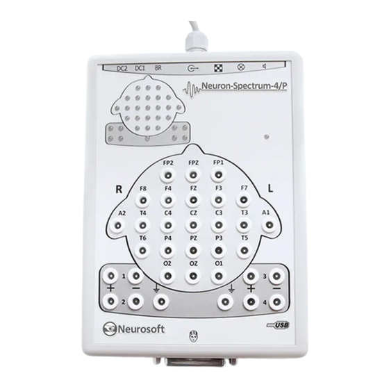
Neuron-Spectrum (Technical Manual) 1.6. Connectors and Indicators The external view of front and side panels of the amplifier unit is represented on Fig. 2, Fig and Fig Touch-proof connectors for electrode cables attachment, LED operation indicator and impedance indicators are located on the front panel (Fig. 2). Fig. - Page 19 Description and Operation The top side panel of the amplifier unit contains the connectors for two direct current channels attachment, the connector for breath sensor attachment, USB cable for the attachment to computer, the trigger socket (trig-in/trig-out) to attach the stimulators of other manufacturers, the connector for pattern-stimulator adapter attachment, the connector for visual stimulator attachment, the connector for the auditory stimulator attachment (Fig...
-
Page 20: Installation
Neuron-Spectrum (Technical Manual) Installation 2.1. Requirements to the Personnel Conducting Systems Installation Digital EEG system installation should be carried out by the person who is empowered by the manufacturer or the technical personnel of the medical institution which is going to use it. It is necessary to remember that digital EEG system mounting accuracy defines safety and quality of operation. - Page 21 Installation · The use of multi-socket electric mains extender without additional protective actions is prohibited. The fact is that the probable break of the circuit of the protective ground of the multi-socket electric mains extender can lead to summation of leakage current in all connected units on their metal parts to dangerous values.
- Page 22 Neuron-Spectrum (Technical Manual) Fig. 6. The sample of digital EEG system placement when connecting to notebook PC. The following abbreviations are used on the figures: · EU – EEG electronic unit; · PU – notebook PC power unit which corresponds to IEC 60601-1; ·...
-
Page 23: Unpacking And Check Of Delivery Set
Installation 2.3. Unpacking and Check of Delivery Set In case the box with the digital EEG system was under conditions of the excessive moisture or low temperature which differs vastly from the working conditions, it is necessary to place it in the room and leave for 24 hours in normal conditions. Unpack the box and take out the digital EEG system components. - Page 24 Neuron-Spectrum (Technical Manual) The general scheme of Neuron-Spectrum-1, Neuron-Spectrum-2, Neuron- Spectrum-3, Neuron-Spectrum-4, Neuron-Spectrum-4/P, CloudEEG connection is shown on Fig. 7. The digital EEG system must be connected to USB port on the PC system unit or USB hub supplied from the electric mains. The connection to the USB connectors on the monitor or keyboard does not provide the correct device operation.
-
Page 25: Proper Use
Proper Use When the message shown on Fig. 9 appears, press the “Next” button. When the installation is completed, press “Finish”. Fig. 9. Completing the found new hardware wizard Proper Use 3.1. Safety Measures when Using the Systems To provide safety measures and exclude the possibility of medical staff’ or patient’... -
Page 26: Setting-Up Procedures
Neuron-Spectrum (Technical Manual) 3.2. Setting-up Procedures Operating Limitations: · Ambient temperature is from +10 to +35°С. · Relative humidity is from 30% to 85%. · Atmospheric pressure is from 70 to 106 kPa. Before power supply switching make sure that digital EEG electronic unit and computer equipment cases have no apparent mechanical failures which can represent a danger. -
Page 27: Exams Performing Using The Systems
Replace it. 3. If the problem was not removed, the electronic unit is out of operation. Consult Neurosoft Ltd. EEG traces recorded in one of the 1. The derivation cable is out of 1. Check the quality of electrode channels are not displayed order. -
Page 28: Actions In Emergency
Neuron-Spectrum (Technical Manual) 3.4. Actions in Emergency In the cases of electrical insulation disturbance of any digital EEG system component which causes the emergency (fire, mechanical failure, flood, medical staff evacuation) and threat of patient or staff electrical shock, it is necessary to de-energize the digital EEG system completely. -
Page 29: Current Repair
Current Repair Current Repair 5.1. General Requirements Digital EEG system repair requires special training of the technical staff and special equipment and service software which you can receive from the manufacturer or the representative of the firm. The repair connected with the EEG electronic unit opening is prohibited. -
Page 30: Photic Stimulator Repair
Neuron-Spectrum (Technical Manual) Fig. 11. Auditory stimulator electrical schematic. 5.5. Photic Stimulator Repair Photic stimulator is examined externally for the cable failure detection. Circuit control from the jack side is conducted according to the schematic in Fig. 12 by the device for LED check. -
Page 31: Visual Pattern-Stimulator Adapter Repair
Current Repair 5.6. Visual Pattern-Stimulator Adapter Repair Pattern-stimulator adapter is examined externally for cable failure detection (Fig. 13). Circuit control from the jack side is impossible. It is necessary to open cable jack unit and check the montage. If the failure is not detected, open the jack unit from the monitor side and measure the resistance of each cable. -
Page 32: Packing And Transportation
Neuron-Spectrum (Technical Manual) Packing and Transportation The package should conform to the accepted one when manufacturing and delivering. In case the factory package is damaged, but the long-term EEG system storage and transportation is expected, respect the following recommendations: · The digital EEG system with operational documentation should be packed in plastic sachets and cardboard boxes. -
Page 33: Delivery Set And Package Data
Delivery Set and Package Data Delivery Set and Package Data Digital neurophysiological system Neuron-Spectrum-1, Digital neurophysiological system Neuron-Spectrum-2, Digital neurophysiological system Neuron-Spectrum-3, Digital neurophysiological system Neuron-Spectrum-4, Digital neurophysiological system Neuron-Spectrum-4/P, Digital neurophysiological system CloudEEG serial number _____________________, is collected and packed according to TC 9441-014-13218158-2006. -
Page 34: Storage Data
Neuron-Spectrum (Technical Manual) 12. Storage Data The systems should be stored in according to the requirement of the present technical manual. Information about the system storage before and in the process of operation is registered in Table 7. Table 7. Storage Data. Date of Storage conditions Position, name... -
Page 35: Warranty
13.4 The manufacturer is obliged to repair the equipment in case of breakdown during the warranty period free of charge. The repair is carried out in the service center of Neurosoft Ltd. (5, Voronin str., Ivanovo, 153032, Russia) only if this registration certificate is provided. - Page 36 Neuron-Spectrum (Technical Manual) 14.2 In case of system return to the service center for the repair or the replacement, the following rules should be observed: · it should be packed so to exclude the possibility of its damage during the transportation;...
- Page 37 Reclamation Data Table 8. Reclamation Data. The date of Brief description of The date of Taken measures Note failure or trouble the trouble reclamation appearance sending...
-
Page 38: Repair Data
Neuron-Spectrum (Technical Manual) 15. Repair Data Table 9. Repair Data. Name and Degree of Date Name of Position, code of imperfection repair name, signature of completion arrival faulty unit works person of repair Carried Accepted out the after the repair repair... -
Page 39: Appendix 1. Electromagnetic Emissions And Immunity
Appendix 1. Electromagnetic Emissions and Immunity Appendix 1. Electromagnetic Emissions and Immunity Guidance and manufacturer’s declaration – electromagnetic emissions The digital system is intended for use in the electromagnetic environment specified below. The customer or the user of the digital system should assure that it is used in such an environment. Emissions test Compliance Electromagnetic environment —... - Page 40 Neuron-Spectrum (Technical Manual) Guidance and manufacturer’s declaration – electromagnetic immunity The digital system is intended for use in the electromagnetic environment specified below. The customer or the user of the digital system should assure that it is used in such an environment. Electromagnetic environment Immunity test IEC 60601 test level...
- Page 41 Guidance and manufacturer’s declaration – electromagnetic immunity The digital system is intended for use in the electromagnetic environment specified below. The customer or the user of the digital system should assure that it is used in such an environment. IEC 60601 test Electromagnetic environment - Immunity test Compliance level...
- Page 42 Neuron-Spectrum (Technical Manual) Recommended separation distances between portable and mobile RF communications equipment and digital system The digital system is intended for use in an electromagnetic environment in which radiated RF disturbances are controlled. The customer or the user of the digital system can help prevent electromagnetic interference by maintaining a minimum distance between portable and mobile RF communications equipment (transmitters) and the digital system as recommended below, according to the maximum output power of the communications equipment.
-
Page 43: Appendix 2. Trigger Input/Output
Appendix 2. Trigger Input/Output Appendix 2. Trigger Input/Output The side panel of Neuron-Spectrum digital system provides a trigger socket for the attachment of stimulators produced by the other manufacturers to the digital system. The devices connected to the trigger socket must have protection class against electrical shock according to IEC 60601-1. - Page 44 Neuron-Spectrum (Technical Manual) Switch on the external stimulator power supply. Run the program, and check the “Third-party firm stimulator” check box on “EEG acquisition” page (in the stimulation parameters settings for the stimulator) (Fig. 15). Fig. 15. The recording start window from external stimulator. In the stimulation settings it is recommended to set those stimulus parameters which the external stimulator has as these particular values are saved together with the trace and taken into analysis.
Need help?
Do you have a question about the Neuron-Spectrum-1 and is the answer not in the manual?
Questions and answers
как заземлять нейро-спектр-1