
Related Manuals for Neurosoft Neuro-Audio


Summary of Contents for Neurosoft Neuro-Audio
- Page 1 Technical Manual Neuro-Audio Digital System for Auditory EP, OAE and Screening PTA TM032.02.003.002 (30.06.2020)
- Page 2 Neurosoft © 2020 5, Voronin str., Ivanovo, 153032, Russia P.O. Box 10, Ivanovo, 153000, Russia Phone: +7 (4932) 95-99-99; + 7 (4932) 24-04-34 Fax: +7 (4932) 24-04-35 E-mail: info@neurosoft.com Internet: www.neurosoft.com...
-
Page 3: Table Of Contents
Contents Introduction ....................... 4 Abbreviations ......................5 Intended Use ......................6 Contraindications ..................... 6 Side Effects ....................... 6 Safety Measures......................7 Description ......................8 1.1. Product Description ..................8 1.2. Principle of Operation ................... 9 1.3. Connectors and Indicators ................10 1.4. -
Page 4: Introduction
Introduction This technical manual is a combined document describing the operation and servicing of Neuro-Audio digital system for auditory EP, OAE and screening PTA (hereinafter referred to as “the system”). The document certifies the technical parameters of the system, which are guaranteed by the manufacturer. -
Page 5: Abbreviations
Abbreviations Abbreviations ADC — analog-to-digital converter VЕМP — vestibular evoked myogenic potential AEP — long-latency evoked potential TEOAE — transient evoked otoacoustic emission ABR — auditory brainstem response MC — microcontroller OAE — otoacoustic emission DPOAE — distortion product otoacoustic emission PC —... -
Page 6: Intended Use
Neuro-Audio (Technical Manual) Intended Use The Neuro-Audio system is intended for use in electrophysiological and audiologic evaluation of hearing and vestibular function as an aid in detecting hearing loss and diagnosing hearing and vestibular related disorders. It can be used for screening and diagnostic applications. -
Page 7: Safety Measures
Safety Measures Safety Measures To provide safety measures and exclude the possibility of electric trauma of medical staff or patients, the medical staff is PROHIBITED to: · use the system which mounting and setting was done improperly, without following this technical manual; ·... -
Page 8: Description
1.1. Product Description The Neuro-Audio is a multifunctional screening and/or diagnostic system that interfaces with the Neuro-Audio.NET audiologic software on a PC. It is a device with built-in 2-channel amplifier for evoked potentials recording, built-in microphone amplifier for OAE recording and a built-in auditory stimulator. The software is used to control the device during testing, to analyze, save and retrieve the recorded test data, to print test reposts. -
Page 9: Principle Of Operation
The block diagram of the system is shown in Fig. 1. Fig. 1. The Neuro-Audio system Biopotentials from the electrodes are transferred to the amplifiers, where they are amplified and then digitized by the analog-digital converter (ADC) delivered to the digital signal processor (DSP) via 4000 V galvanic isolation. -
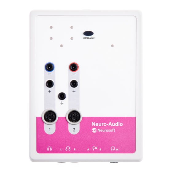
Page 10: Connectors And Indicators
The impedance indicators glow in the impedance measurement mode. You can switch to this mode using the Neuro-Audio.NET program settings (see user manual) or the Impedance measurement button. The colour of indicators means the quality of the electrode placement. - Page 11 Do not attach the headphones to the 3.5 stereo and 6.3 mono connectors simultaneously. It leads to incorrect stimulus volume in the headphones. There are two types of connectors to attach OAE probe: mini DIN 6 manufactured by Neurosoft (Russia) and mini DIN 8 manufactured by Etymotic Research (USA).
- Page 12 Fig. 4. Bottom panel Designations shown in Fig 1 — connectors for headphones; 2 — connector for OAE probe (Neurosoft); 3 — connector for OAE probe (Etymotic Research); 4 — connector for bone vibrator. The front and back panels of the bone conduction amplifier are shown in Fig. 5 and Fig.
-
Page 13: Labeling
Description On/off button Connector for PSU-9 power supply unit Fig. 6. Back panel of bone conduction amplifier Table 1. The description of colors of bone conduction amplifier indicators Color of indicator Description Ready indicator: green The unit is on and ready for operation (stimulation). Charge indicator: green Ready indicator: no illumination Discharged battery. - Page 14 Neuro-Audio (Technical Manual) - mark of conformance to 2012/19/EC “On waste electrical and electronic equipment (WEEE)” directive. – number according to catalogue by ISO 15223-1. - serial number by ISO 15223-1. - date of manufacture by ISO 15223-1. - manufacturer’s name and address ISO 15223-1.
-
Page 15: Preparing The Product For Use
Preparing the Product for Use Fig. 9. DataMatrix barcode Data Matrix is a two-dimensional matrix barcode, consisting of black and white “cells” or modules of different brightness arranged in either a square or rectangular pattern. The DataMatrix barcode is described in ISO/IEC 16022:2006 standard. To decode the data on device, DataMatrix barcode can be read quickly by a barcode reader or by the smartphone camera as a two-dimensional image. -
Page 16: Reducing Electrical Noise
Neuro-Audio (Technical Manual) · Place the electronic unit on the maximum possible distance from power cables, switchboards, different powerful electrical devices which emit electromagnetic fields of mains frequency. Requirements to mains: · The system should be supplied from 230 V mains equipped with TN-S or TN-C-S ground system (according to IEC 60364-1). - Page 17 If the ground is not connected or even missing, the ABR recordings will be distorted greatly. The Neuro-Audio digital system is connected to the ground lead via a ground contact of tripolar outlet. If the ground lead is not connected, the digital system will pick up electrical noise/interference.
-
Page 18: Unpacking And Checking Delivery Set
Neuro-Audio (Technical Manual) 3.2. The voltage between the phase (hot) and ground sockets must be stable (230 V for Europe/110 V for US (country specific). It is the same voltage as in item 3.1 (see above) with a deviation of max 5 V. -
Page 19: Assembly And Connection To Computer
If the electronic media with the software is not available, please contact your local dealer. The list of authorized Neurosoft dealers can be found here: https://neurosoft.com/en/pages/dealers. The digital system consists of the electronic unit and can be supplied with the patient button depending on the delivery set variant (Fig. - Page 20 8 — to USB connector, 9 — PC system unit. Place the holder to the testing site as near as possible and fix the Neuro-Audio electronic unit on it. Connect the required equipment (according to Fig. 10). The electrical units can be connected to PC when the power supply is on or off.
-
Page 21: Proper Use
Neuro-Audio electronic unit with a cable (NS032103.011). The bone vibrator should be connected to the corresponding connector of the bone conduction amplifier (Fig. 5 and Fig. 6). And the bone conduction amplifier itself should be connected to the PSU-9 power supply unit (NS057201.009) to operate from the mains or you can... -
Page 22: Performing Tests
Neuro-Audio (Technical Manual) is on, when the operating system has been loaded and the Neuro-Audio.NET software is started. 3.2. Performing Tests Before testing, set up the digital system and other equipment following the recommendations in the user manual depending on a test type. -
Page 23: Troubleshooting
Program message: Electronic unit of Check whether the electronic “Link error: Neuro-Audio is not the Neuro-Audio digital unit is connected to PC. If connected or defective”. system is not connected to there are no connection... - Page 24 Neuro-Audio (Technical Manual) Table 2(continued) Trouble Symptom Possible Cause Way of Removal Program message: The system was Check the connection of “USB transfer error. Check disconnected during the the Neuro-Audio digital the connection and restart recording or failed when system and restart the signal the system”.
-
Page 25: Actions In Emergency
Maintenance Table 2 (continued) Trouble Possible cause Way of Removal The bone conduction internal circuit To restart the operation, set amplifier has been left in the power supply unit has the switch to position “0” and the ON mode for more than 8 switched because connect the external AC power... -
Page 26: User Maintenance
Neuro-Audio (Technical Manual) 4.2. User Maintenance The user maintenance of the system includes the external examination, check of connectors and cables, cleaning and disinfection according to recommendations stated in section 4.4 “Disinfection”. 4.3. Periodic Maintenance 4.3.1. Checking of OAE Channel with Test Cavity The checking of OAE channel with a test cavity should be performed in a quiet room. - Page 27 Maintenance calibration (the Seal control mode) make sure that two similar traces of stimulus spectrum from the first and second telephones appear on the screen (Fig. 14). Fig. 14. Frequency response calibration When the test is over, the result should be REFER. There must be no emission for all frequencies (Fig.
-
Page 28: Checking Of Oae Probe
The check is performed in a special OAE probe check mode. In this mode the comparison of OAE probe responses with already set responses is carried out. Start the Neuro-Audio.NET program, execute the Setup|Change menu command. Select the Hardware page and press OAE Probe Check (Fig. 16). - Page 29 Maintenance The OAE probe check window appears (Fig. 17). Fig. 17. The OAE probe check window Connect the OAE probe to the system, take off the OAE probe tip and insert the OAE probe into the test cavity as far as it can go. Press Check to start checking.
- Page 30 Neuro-Audio (Technical Manual) · If two first steps don’t work, replace the OAE probe tip. · If the tip replacement doesn’t work, replace the OAE probe. After the OAE probe replacement, save its specifications in the OAE Probe Check window (Fig. 17). Press New and wait until the progress bar reaches its end and the Done message appears (Fig.
-
Page 31: Calibration Of Stimulus Intensity Within Free Field
During the calibration follow the steps below. Run the Neuro-Audio.NET program. In the main menu select Setup|Calibration mode… Enter the password for the setting/calibration mode (see section 4.2 “Calibration mode in Neuro-Audio.NET software” of “Neuro-Audio” calibration... - Page 32 Neuro-Audio (Technical Manual) Do not tell your password to anyone except those who will make calibration. In the calibration mode create a new calibration file (press “+” in the bottom left corner of the calibration window). Fill in the metadata of the calibration file: 1.
-
Page 33: Disinfection
Clean the device only when it is switched off (USB cable or power supply is disconnected). Clean the electrode cables only when they are detached from the Neuro-Audio electronic unit. Do not use abrasive or solvent silicon-based cleaning agents, scrubbing pads or other abrasive applicators. -
Page 34: Lifetime
The auditory transducer (headphones) is cleaned and disinfected according to the transducer manufacturer’s instruction manual. To clean and disinfect the Neuro-Audio electronic unit, electrode cables, bone vibrator, bone conduction amplifier unit and PSU-9 power supply unit please follow the instructions below: 1. -
Page 35: Disposal
Acceptance, Delivery Set and Package Data The Neuro-Audio digital system for auditory EP, OAE and screening PTA is collected and packed according to the requirements of design documentation. Packed by ___________________... -
Page 36: Warranty
11.4. The manufacturer is obliged to repair the system in case of failure during the warranty period free of charge. The repair is carried out in Neurosoft service center (5, Voronin str., Ivanovo, 153032, Russia) in compliance with the procedure stated in section 9 “Reclamation”. -
Page 37: Reclamation
Reclamation Reclamation 9.1. The written notification to Neurosoft in case of the system failure should include the following information: · the customer’s name and address, · the serial number of the system (specified on the label and in section 7 “Acceptance, Delivery Set and Package Data”), ·... -
Page 38: Annex 1. Main Specifications
Neuro-Audio (Technical Manual) Annex 1. Main Specifications The main specifications of the system are given in Table 4. Table 4. Main specifications Parameter Value EP channels Number of channels Input voltage range 20 µV to 50 mV The admissible error of voltage measurement should be within ·... - Page 39 Annex 1. Main Specifications Table 3 (continued) Parameter Value Tone burst stimulation: · 20–10000 Hz tone · 0.05–50 ms stimulus duration Click stimulation: · 50–5000 µs with the admissible stimulus duration relative deviation of ± 2 %. Continuous tone stimulation: pure tone;...
- Page 40 Neuro-Audio (Technical Manual) Table 3 (continued) Parameter Value f2/f1 DPOAE frequency ratio 1.1–1.3 Stimulus 3rd order intermodulation -80 dB General parameters and specifications Interface Supply voltage: · 5 V DC electronic units · 220/230 V AC (50 Hz) desktop PC-based computer ·...
- Page 41 Annex 1. Main Specifications Table 3 (continued) Parameter Value Conformance to technical standards Reference zero for calibration of audiometric EN ISO 389-1:2000 equipment EN ISO 389-2:1996 EN ISO 389-3:2016 EN ISO 389-5:2006 EN ISO 389-6:2007 EN ISO 389-8:2004 Stimulus types EN 60645-1:2015 EN 60645-3:2007 Tone audiometry (PТA)
-
Page 42: Annex 2. Delivery Set
The accessories and bought articles are also delivered. The delivery set is shown in Table 5 and Table 6 where 1 describes base delivery set, 2 – Neuro-Audio/ABR delivery set, 3 – Neuro-Audio/OAE delivery set, 4 – Neuro-Audio/PTA delivery set. - Page 43 Electrode abrasive paste for Everi, 160 g (Italy) – – skin preparation 1527-2, Transpore Medical tape (3M Company, 3M Health – Care, USA) Software: Neuro-Audio.NET software license with NS001.221023 – – Neuro-Audio.NET/ABR module Neuro-Audio.NET software license with NS001.221643 – –...
- Page 44 Neuro-Audio (Technical Manual) Table 5 (continued) Quantity, pcs. Order code or main Name specification Neuro-Audio.NET software license with NS001.219921 – – Neuro-Audio.NET/OAE module Neuro-Audio.NET software license with NS001.219931 – – – Neuro-Audio.NET/PTA module Operational Documentation: “Neuro-Audio” technical TM032.02.003.002 manual “Neuro-Audio.NET” user UM032.01.005.001...
- Page 45 Annex 2. Delivery Set Table 6. Equipment and software included in base delivery set at customer’s request Quantity, pcs. Order code or main Name specification Bone vibrator NS032221.002 Bone vibrator NS032998.001 Set of eartips (pediatric) NS007998.001 – – SU-6 stand for electronic unit NS016998.011 Disposable surface electrode F3001NECG (FIAB, Italy)
- Page 46 Neuro-Audio (Technical Manual) Table 6 (continued) Quantity, pcs. Order code or main Name specification Bone conduction amplifier NS032201.012-02 Bone conduction amplifier cable NS032103.011 PSU-9 power supply unit NS057201.009 Equipment for OAE Study: OAE probe OAE-02-02 NS006355.003-01 – – OAE probe tip NS006221.001...
-
Page 47: Annex 3. Electromagnetic Emission And Immunity
Annex 3. Electromagnetic Emission and Immunity Annex 3. Electromagnetic Emission and Immunity Guidance and manufacturer’s declaration – electromagnetic emissions The digital system is intended for use in the electromagnetic environment specified below. The customer or the user of the digital system should assure that it is used in such an environment. Emissions test Compliance Electromagnetic environment —... - Page 48 Neuro-Audio (Technical Manual) Guidance and manufacturer’s declaration – electromagnetic immunity The digital system is intended for use in the electromagnetic environment specified below. The customer or the user of the digital system should assure that it is used in such an environment.
- Page 49 Annex 3. Electromagnetic Emission and Immunity Guidance and manufacturer’s declaration – noise immunity The system is intended for operation in electromagnetic conditions environment described below. The customer or user of the system should provide the system operation in the specified electromagnetic conditions environment. Immunity test IEC 60601 Compliance...
- Page 50 Neuro-Audio (Technical Manual) Recommended separation distances between portable and mobile RF communications equipment and screening system The system is intended for use in an electromagnetic environment in which radiated RF disturbances are controlled. The customer or the user of the system can help prevent electromagnetic interference by...
-
Page 51: Annex 4. Trig In/Out
Annex 4. Trig In/Out Annex 4. Trig In/Out On the side panel of the digital system there is a trig in/out to attach stimulators of other manufacturers. The connected devices must have protection class against electrical shock according to IEC 60601-1:2012. The cables to connect the devices of other manufacturers are not included in the delivery set and must be produced according to the recommendations stated in this annex. - Page 52 Neuro-Audio (Technical Manual) The external stimulators are connected to the trig in as follows: Connect the external stimulator to the trig in with a cable. Switch on the external stimulator power supply. Run the program and check the Third-party firm stimulator checkbox on the Hardware tab (Fig.
- Page 53 Annex 4. Trig In/Out Connect the external stimulator to the trig out with a cable. Switch on the external stimulator power supply. Run the program and uncheck the Third-party firm stimulator checkbox in the stimulation parameters settings. In the stimulation settings it is recommended to set those stimulus parameters which the external stimulator has as these particular values are saved together with the trace and taken into analysis.
Need help?
Do you have a question about the Neuro-Audio and is the answer not in the manual?
Questions and answers