Table of Contents
Advertisement
Quick Links
Advertisement
Table of Contents

Subscribe to Our Youtube Channel
Related Manuals for HydroHoist HYDROLOCKER 78


Summary of Contents for HydroHoist HYDROLOCKER 78
- Page 1 1034817 REVISION A...
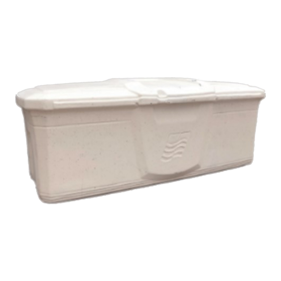
- Page 2 Installation of the HYDROLOCKER 78” is simple due to its lightweight design and ease of operation.
-
Page 3: Table Of Contents
TABLE OF CONTENTS PRODUCT INFORMATION PAGE PRE-INSTALLATION CONSIDERATIONS _______________________________ 4 GENERAL SPECIFICATIONS ________________________________________ 5 REQUIRED TOOLS _______________________________________________ 6 TORQUE SPECIFICATIONS _________________________________________ 6 PARTS LIST _____________________________________________________ 7 VENT INSTALLATION _____________________________________________ 8 PIN INSTALLATION _______________________________________________ 9 SHOCK INSTALLATION ___________________________________________ 10 HOSE HANGER INSTALLATION ____________________________________ 11 DOCK BRACKET INSTALLATION ____________________________________ 12 WARRANTY &... -
Page 4: Pre-Installation Considerations
PRE-INSTALLATION CONSIDERATIONS Due to its size, the following determinations must be made before installing a HYDROLOCKER: • Location on the Dock (remote or on-site) • Method of transport to Dock or site • Equipment required to safely assemble, transport, and mount the HYDROLOCKER Remote assembly and then completing final assembly at the Dock or Site might be logistically simpler. -
Page 5: General Specifications
Chart 1: General Specification of the HYDROLOCKER 78 WEIGHT WIDTH LENGTH DEPTH VOLUME 95 LBS 34-5/8” 78-5/32” 26-5/8” CUBIC FEET... -
Page 6: Required Tools
Chart 2: Required Tools Safety Glasses Drill 25/64” Drill Bit Gloves Hole Center Punch (or Scribe) 17/64” Drill Bit 7/16” Socket Wrench / Driver Thread Sealant (where necessary) 7/16” Box End Wrench 9/16” Socket Wrench / Driver Needle Nose Pliers 9/16”... -
Page 7: Parts List
Chart 4: PARTS LIST—HYDROLOCKER HYDROLOCKER Quanti- Part Description BASE HYDROLOCKER 1033927 1033925 HYH LOCKER-HYDROLOCKER-78 IN-WITH BIN 1033926 HYH BIN-HYDROLOCKER-78 IN 1033933 HYH LID-HYDROLOCKER-78 IN 1034857 HYH KIT-HARDWARE-HYDROLOCKER-78 HYDROLOCKER SHOCK KIT 1033928 1033936 HYH SHOCK-GAS-WELDED END 1033937 HYH PIN-SHOCK MOUNT-.312 X 1.25 SS 1033938 HYH PIN-SHOCK MOUNT-.312 X 2.00 SS 1033939... -
Page 8: Vent Installation
VENT INSTALLATION Part # Parts Required Quantity Kit# Parts Required Quantity 1034898 HYDROLOCKER VENT HYDROLOCKER HARDWARE KIT 1034857 STEP 1 STEP 2 STEP 3 VENT INSTALLATION 1. Align Vent with hole and insert Vent 2. Press firmly into position 3. Bend Tabs over (use Needle Nose Pliers) 4. -
Page 9: Pin Installation
PIN INSTALLATION Part # Parts Required Quantity Kit# Parts Required Quantity 1033935 HYDROLOCKER PIN HYDROLOCKER HARDWARE KIT 1034857 STEP 1 STEP 2 CORRECTLY INSTALLED PIN INSTALLATION 1. Align Pin with hole in Locker and Lid 2. Insert Pin through the Locker Hinge into Lid Hinge: apply firm pressure (a Hammer may be used to gently tap through) 3. -
Page 10: Shock Installation
SHOCK INSTALLATION Kit # Parts Required Quantity Part # Hardware Required Quantity 1033936 HYH SHOCK-GAS-WELDED END 1033928 HYDROLOCKER SHOCK KIT 1033937 HYH PIN-SHOCK MOUNT-.312 X 1.25 SS 1033938 HYH PIN-SHOCK MOUNT-.312 X 2.00 SS 1033939 HYH PIN-COTTER-1/8 X 1/2 SS STEP 1 &... -
Page 11: Hose Hanger Installation
HOSE HANGER INSTALLATION Part # Hardware Required Quantity Kit# Parts Required Quantity BACKING PLATE 1033932 35000010 HYDROLOCKER HOSE HANGER KIT 1/4” FLAT WASHER 30080008 1/4” NUT 30010005 1/4” BOLT) 30000032 HOSE HANGER 15000026 STEP 2 STEP 3 HOSE HANGER INSTALLATION 1. -
Page 12: Dock Bracket Installation
DOCK BRACKET INSTALLATION Part # Parts Required Quantity Part # Hardware Required Quantity 1033924 DOCK BRACKET Flat Fender Washer 3/8” X 1-1/2” OD SS 1033941 1033940 HARDWARE KIT Nut 3/8-16” 1033943 Hex Bolt 3/8-16 X 2” 1042940 Lock Washer 3/8” 1033942 STEP 1 DOCK BRACKET INSTALLATION... - Page 13 DOCK BRACKET INSTALLATION CONT. 38-5/8” BETWEEN BRACKETS STEP 2B STEP 3A DOCK BRACKET INSTALLATION 2A. Use the Dock Bracket for a template to drill the mounting holes on the dock face 2B. Locate the first Dock Bracket in the desired location on the Dock (see picture above) NOTE: Verify Bracket is Square as well as Level to the dock 2C.
- Page 14 DOCK BRACKET INSTALLATION CONT. STEP 4B STEP 4D DOCK BRACKET INSTALLATION 4A. Set the HYDROLOCKER on the Brackets aligned to the dock in the final installation location 4B. Mark ALL hole locations on the Brackets (a Center Punch may be used: see picture above) 4C.
- Page 15 DOCK BRACKET INSTALLATION CONT. STEP 5A STEP 5B STEP 5C STEP 5D STEP E DOCK BRACKET INSTALLATION 5A. Place Fender Washers on Dock Side of the 3/8” Bolts (see picture above) 5B. Insert Bolts & Washers through the HYDROLOCKER floor and through the Brackets (see picture above) NOTE: DO NOT TIGHTEN BOLTS AT THIS TIME: HAND TIGHTEN 5C.
-
Page 16: Warranty & Registration
HydroHoist® (g) Damaged during shipment (h) Damaged by any other abuse or misuse by the user *Terms and conditions can change without notice. For the latest warranty terms, contact HydroHoist Cus- tomer Service at customerservice@boatlift.com Parts and Customer Service Contact...
Need help?
Do you have a question about the HYDROLOCKER 78 and is the answer not in the manual?
Questions and answers