Table of Contents
Advertisement
Quick Links
Advertisement
Table of Contents

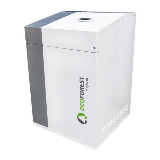
Summary of Contents for ECOFOREST ecoSMART e-system
- Page 1 USER MANUAL MODEL: SERVICE CONTACT:...
-
Page 3: Table Of Contents
User manual ecoSMART e-system Contents 1. General information ............................... 2 1.1. Safety considerations .............................. 2 1.2. Steps to follow in case of fire ..........................3 1.3. Maintenance ................................3 2. System diagram ..............................4 3. Controller guide ..............................6 3.1. Control panel ................................6 3.2. -
Page 4: General Information
DANGER! The ecoSMART e-system has been designed to work with ecoGEO heat pumps and a serie of commercial trades and installations designed for the production of energy from renewable sources or similar equipment. -
Page 5: Steps To Follow In Case Of Fire
User manual ecoSMART e-system 1.2. Steps to follow in case of fire Electrical devices may ultimately cause a fire due to faulty installation or improper use of the equipment. The measures taken must ensure the safety of persons in the first place, as well as prevent further material damage. In case of fire inside or near the e-system,... -
Page 6: System Diagram
Figure 2.1. General diagramo f the e-system The proprietary software incorporated in the ecoSMART e-system allows to choose from a range of functions to maximise the performance of your installation. - Page 7 Control of electrical surplus. The ecoSMART e-system is able to determine when we are facing an energy surplus situation. In this case, and under a series of configurable conditions for the beginning and end of the regulation, the control will adjust the consumption of the heat pump to take advantage of this surplus in the production and storage of thermal energy, so that it is obtained with less consumption when the electricity production from renewable sources falls.
-
Page 8: Controller Guide
User manual ecoSMART e-system 3. Controller guide • Depending on the software version and configuration established by the technical service, there may be screens or contents that are not shown. • If the following screen appears when accessing menu, this means that the service requested has not been enabled by the technical service. -
Page 9: Main Screen
The controller is in a state of emergency because of an active alarm. The controller still run but the alarm warns us of abnormal behavior and registers it. 3.4. Operating modes The operating modes active in the ecoSMART e-system are reflected in the main screen and give a quick reading of the behavior of the control at any time. SURPLUS CONTROL Mode... - Page 10 User manual ecoSMART e-system REGULATION signal An output for speed control of the heat pump compressor has been activated. NON CRITICAL LOAD ACTIVE signal Relay output to non-critical load enabled (up to four loads).
-
Page 11: List Of Installer Menu
User manual ecoSMART e-system 3.6. List of installer menu Follow the instructions below to browse through the various user menus. Each menu has a series of screens that are used to change heat pump STATUS and OPERATION MODE, adjust comfort parameters and view desired information. -
Page 12: Parameters Adjustment
User manual ecoSMART e-system 3.7. Parameters adjustment Take the following steps to change a parameter: Search for the screen containing the parameter that needs adjusting (figure 5.4). With the cursor in position 1 press on to enter the screen and move the cursor to the parameter in position 2. -
Page 13: Surplus Configuration Menu
User manual ecoSMART e-system Daily saving time Daily saving time Enable: Transition time: min The settings of automatic daylight time change between seasons (autumn-winter / spring- Start: LAST SUNDAY summer) can be adjusted. in MARH : End: LAST SUNDAY in OTOBER 3:... -
Page 14: Alarms Menu
User manual ecoSMART e-system /7 Grid balance Grid balance Real: 7kW Displays information regarding the actual instantaneous balance read at the border, the Surplus: kW set for surplus regulation and the configured consumption limit. onsum limit: -44kW Power meters Power meters onsumption:... - Page 15 User manual ecoSMART e-system User menu Non-critical loads Information Alarms Alarms Alarms Lost comm This screen displays the active alarms. The button illuminates. with the Modbus slave Reset alarms It allows us to reset alarms once solved. Reset alarms Reset alarms:...
-
Page 16: Simbols
User manual ecoSMART e-system 4. Simbols e-system On/Off Status. Alarm. e-system surplus control mode active. e-system consumption control mode active. Active heat pump compressor regulation. Active non-critical load. Generated power. Consumption/Injection from/to the public grid. 5. Alarms and troubleshooting 5.1. Active alarms An alarm icon on the main display screen indicates a malfunction of the e-system. -
Page 17: Technical Specifications
User manual ecoSMART e-system 6. Technical specifications DC Input Max. DC recommended power 5.000 Number of MPPT´s Strings per MPPT MPPT voltage range 125-530 DC max. voltage DC rated voltage Max. current per MPPT Max. short circuit current per MPPT... - Page 18 User manual ecoSMART e-system Battery module Type LiFePO4 Rated voltage Rated capacity 2.400 Usable capacity 2.200 Charge voltage 52,5-54 Discharge voltage 45-54 Recommended charge/discharge current Max. charge/discharge current Charge/discharge peak current (15 s) Charge 0-50 ℃ Work temperature Discharge -10-50 ℃...
-
Page 19: Warranty And Technical Service
7.1. Manufacturer's warranty ECOFOREST is liable for lack of conformity of the product or its spare parts, in compliance with the current regulations of the country where the product is purchased. The warranty is only valid in the country where the product is purchased. - Page 20 NOTES : ..........................................................................................................................................................................................................................................................................................................................................................................................................................................................................................................................................................................................................................................................................................................................................................................................................................................................................................................................................................................................................................................................................................................................................................................................................................................................
- Page 21 ........................................................................................................................................................................................................................................................................................................................................................................................................................................................................................................................................................................................................................................................................................................................................................................................................................................................................................................................................................................................................................................................................................................................................................................................................................................................................................................................
- Page 23 ECOFOREST GEOTERMIA, S.L. Poligono Porto do Molle/Rúa das Pontes 25 36350 - Nigrán - Pontevedra (Spain) Tel.: +34 986 262 184 / +34 986 417 700 Fax: +34 986 262 186 e-mail: Info@ecoforest.es http://www.ecoforest.es The manufacturer reserves the right to make any necessary changes to the contents of this manual without prior notice.


Need help?
Do you have a question about the ecoSMART e-system and is the answer not in the manual?
Questions and answers