Table of Contents
Advertisement
Quick Links
Advertisement
Table of Contents

Related Manuals for MOGlabs QRF041


Summary of Contents for MOGlabs QRF041
- Page 1 Quad RF Synthesizer QRF041/QRF241 Version 0.2.0, Rev 2 hardware...
- Page 2 MOGL abs. Contact For further information, please contact: MOG Laboratories P/L MOGLabs USA LLC 49 University St 419 14th St Carlton VIC 3053 Huntingdon PA 16652 AUSTRALIA +61 3 9939 0677 +1 814 251 4363 info@moglabs.com...
- Page 3 We hope that you enjoy using the , and please let us know if you have any suggestions for improvement in the or in this document, so that we can make life in the lab better for all. MOGL abs, Melbourne, Australia www.moglabs.com...
-
Page 5: Safety Precautions
Safety Precautions Safe and effective use of this product is very important. Please read the following safety information before attempting to operate. Also please note several specific and unusual cautionary notes before using the MOGL , in addition to the safety precautions that are standard for any electronic equipment. -
Page 6: Protection Features
Protection Features MOGL includes a number of features to protect you and your device. Open/short circuit Each output should be connected to a 50 Ω load where possible. The high-power output can tolerate open-circuit, but should not be short-circuited. Mains filter Protection against mains transients. Temperature Several temperature sensors control the fan and will trigger a shutdown if the temperature exceeds a safe limit. -
Page 7: Rohs Certification Of Conformance
RoHS Certification of Conformance MOG Laboratories Pty Ltd certifies that the MOGL abs Diode Laser Controller (Revision 3) is RoHS-5 compliant. MOG Laboratories no- tes, however, that the product does not fall under the scope defined in RoHS Directive 2002/95/EC, and is not subject to compliance, in accordance with DIRECTIVE 2002/95/EC Out of Scope;... -
Page 8: Table Of Contents
Contents Preface Safety Precautions Protection Features RoHS Certification of Conformance Getting started 1 Introduction 1.1 Operating modes ..... 1.2 Feature compatibility ....2 Connections and controls 2.1 Front panel controls . - Page 9 Contents 5 Table mode 5.1 Operational principle ....5.2 External trigger ..... . 5.3 Re-arm and restart .
- Page 10 Contents viii...
-
Page 11: Getting Started
Getting started 1. Connect to mains power using the supplied cord. 2. Power on the device using the rocker switch on the rear. 3. Wait for the device to boot and the menu system (§2.2) to be displayed. 4. Set power limits for each channel using the Options menu. Devices are shipped with a 30 dBm limit that should be adjus- ted as required. - Page 12 Getting started...
-
Page 13: Introduction
1. Introduction MOGL consists of an AD9959 , which provides four in- dependent direct digital synthesizer (DDS) sources, and a 2 W am- plifier for each channel. The frequency, amplitude and phase of each output is software-controlled via a microcontroller, which can be adjusted in real-time using the front-panel control knobs, or via a scripting language over ethernet or . -
Page 14: Operating Modes
Chapter 1. Introduction The device allows analogue modulation through analogue-to-digital converters ( ADCs ) with anti-aliasing filters. When modulation is ena- bled, the microcontroller reads the value of the modulation signal and uses that value to adjust the frequency, power and/or phase. includes memory for storing complex waveform sequences, where each step in the sequence defines the frequency, power, phase and duration of that step. -
Page 15: Feature Compatibility
1.2 Feature compatibility : Advanced mode Advanced mode provides direct user-control of the and its in- ternal registers via the command. Direct programming of each is complex and not necessary for most applications; it requires careful reference to the AD9959 datasheet and manual calculation of the hardware registers. - Page 16 Chapter 1. Introduction...
-
Page 17: Connections And Controls
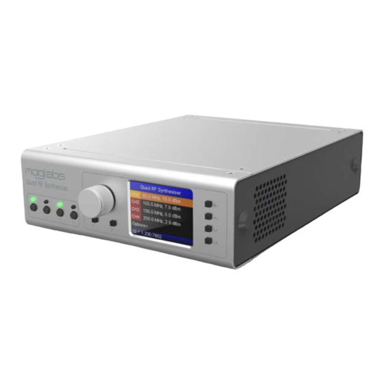
2. Connections and controls 2.1 Front panel controls 4 Ch. RF Sythesizer Ch. 1 Ch. 2 Ch. 3 Ch. 4 Figure 2.1: Front-panel layout of devices. The front-panel includes an interactive menu system for displaying the device state and controlling its settings. Each channel has an individual on/off... -
Page 18: Menu System
Chapter 2. Connections and controls 2.2 Menu system The main menu (Figure 2.2) shows the current mode and status of each channel. In basic ( ) mode, the current frequency and power of each channel is displayed, as well as any active modulation. Pressing the button with a channel selected will open the sub- menu to adjust settings for that channel (Figure 2.3). - Page 19 2.2 Menu system The color of each menu item represents its purpose, as listed below. White Static value, displayed for diagnostic purposes. Yellow Adjustable value, modified using the encoder wheel. Orange Currently selected channel. Blue Submenu, entered with the button. Green Command, executed by the button.
-
Page 20: Rear Panel Controls And Connections
Chapter 2. Connections and controls The overall brightness of the display can be set with the contrast value in the Options menu. The display also includes a sleep timer that dims the display if it hasn’t received input in a given period of time. -
Page 21: Internal Dip Switches
2.4 Internal DIP switches CLK IN can be synchronised to a high-performance external clock input via this connector. The input is 50 Ω terminated, and the provided 25 MHz reference must be between 0 and +5 dBm. RJ45/USB-A Ethernet (TCP/IP 10/100 Mb/s) and communications jacks. - Page 22 Chapter 2. Connections and controls...
-
Page 23: Mogrf Host Software
3. MOGRF host software The mogrf software package provides a simple user interface to the basic behaviour of devices, with the ability to issue commands, run scripts, control tables, and apply firmware updates. This is the same software used to control devices. -
Page 24: Device Commander
Chapter 3. MOGRF host software 3.2 Device commander The Device commander is an interactive terminal for issuing com- mands and queries to your device and displaying the result (Figure 3.2). The accepted commands and their functions are listed in Appendix C. Type statements into the Command box and exe- cute them by pressing the key or clicking . -
Page 25: Mogrf Main Window
3.3 MOGRF main window 3.3 MOGRF main window The main window of mogrf is shown below. The channels are dis- played side-by-side, with information and controls that depend on the current operational mode of each channel. Figure 3.3: The main window of mogrf, showing are in basic mode, and are in table mode. - Page 26 Chapter 3. MOGRF host software 3.3.1 File menu Device command Starts the Device commander (§3.2) for interactive execution of in- structions to control the device. Upload firmware Starts the firmware update application to upload and install upda- tes on the device. The procedure for applying firmware updates is described in detail in Appendix B.
- Page 27 3.3 MOGRF main window Figure 3.5: Use the Modulation dialog in the mogrf application to change the modulation settings for each channel Each channel can have a primary and secondary modulation enabled (§4.3), which use the associated physical modulation input mapping. The gain can be set using the slider or by entering a value directly.
- Page 28 Chapter 3. MOGRF host software...
-
Page 29: External Modulation
4. External modulation supports external modulation of the mode through the modulation input connectors on the back-panel. Frequency, amplitude and phase modulation of the are supported. WARNING: The modulation inputs are nominally ±1V, and can be permanently damaged by applying higher voltages. Disconnected inputs are floating and can cause unexpected results when modulation is enabled. -
Page 30: Modulation Gain
Chapter 4. External modulation 4.2 Modulation gain The modulation depth is controlled by the “gain” and is set using GAIN command. Each channel has a separate gain control for each modulation mode (amplitude, frequency or phase), which can be negative to indicate that the modulation action is inverted. The gain can be specified with physical units, which corresponds to the modulation produced for +1V input. - Page 31 4.3 Dual modulation Each physical input can only be used for one purpose at a time, so if an input is used for primary modulation on a channel, it can- not simultaneously be used for secondary modulation on a separate channel.
- Page 32 Chapter 4. External modulation The modulation mapping is stored in non-volatile memory, but it is strongly recommended that any setup scripts explicitly include the modulation input mapping to prevent confusion. The active purpose of the modulation inputs can be verified using MAPMOD command.
-
Page 33: Pid Stabilisation
4.4 PID stabilisation 4.4 PID stabilisation In addition to direct modulation, the also provides control loops which can be used in conjunction with an to perform intensity (also called noise eating) or frequency stabilisation of a laser. Each channel has an independent controller, which acts to drive an error signal provided to the modulation input towards zero by adjusting the frequency, power or phase as appropriate. - Page 34 Chapter 4. External modulation A clamping circuit should be used to ensure that the signal fed into does not exceed the ±1 V modulation input tolerance, as this can damage the input ADCs For convenience, MOGL abs produces a signal-conditioning board B3122 ) available as an optional extra, which provides: 1.
-
Page 35: Ttl Switching
4.5 TTL switching 4.5 TTL switching A versatile feature of the is the ability to switch the response to an external input such as a tactile switch or a trigger for device synchronisation. The switching bypasses the mi- crocontroller, enabling very low latency switching to be achieved (Figure 4.3). - Page 36 Chapter 4. External modulation...
-
Page 37: Operational Principle
5. Table mode Table mode performs sequential execution of up to 8191 instructi- ons with precise timing. This enables generation of complicated pulse sequences, custom envelope shapes, and automated control of experiment sequences through digital I/O. 5.1 Operational principle Each channel has its own independent table comprising a number of entries that describe the frequency, amplitude and phase of the rf output at each step. - Page 38 Chapter 5. Table mode MODE,1,TSB TABLE,CLEAR,1 TABLE,APPEND,1,20MHz,0dBm,0,0x1 TABLE,APPEND,1,50MHz,5dBm,0,0x1 TABLE,APPEND,1,100MHz,10dBm,0,0x1 TABLE,APPEND,1,50MHz,-5dBm,0,0x1 TABLE,APPEND,1,20MHz,5dBm,0,0x1 TABLE,APPEND,1,20MHz,0x0,0,0x1 TABLE,ARM,1 TABLE,START,1 Listing 5.1: Demonstration of simple table mode commands. Figure 5.1: Output waveform generated by simple table mode example. Typically more complicated pulse sequences are of interest, such as generated shaped envelopes with frequency sweeps.
-
Page 39: External Trigger
5.2 External trigger Figure 5.2: Demonstration of a more complicated table sequence involving a shaped pulse with frequency chirp. 5.2 External trigger An external trigger can be used in table mode to synchronize with other devices. In thise mode the instruction will be repeated until a falling trigger is detected on the input. - Page 40 Chapter 5. Table mode Furthermore, the table can be repeated continuously by enabling TABLE,RESTART option. This will cause the table to immediately re-execute after it has been rearmed, although an initial hardware or software trigger must be provided to begin the first execution.
-
Page 41: A Specifications
A. Specifications Specification Parameter RF characteristics +33 dBm/+12 dBm (241/041 models) Max output power Ω Output impedance 10-bit resolution Amplitude control 10 to 200 MHz Frequency 32-bit resolution; 0.116 Hz steps Frequency control ◦ ±25 ppm (0 to 50 Frequency stability 0 to 2π... - Page 42 Appendix A. Specifications Digital input (per channel) hardwired, positive logic only RF on/off input to continue table execution Trigger input 2.2 V TTL input high 0.6 V TTL input low 6.5 V Absolute max in -0.5 V Absolute min in Table mode Min.
-
Page 43: B Firmware Upgrades
B. Firmware upgrades From time to time, MOGL abs will release firmware updates that enable new functionality or address issues. This section provides instructions on how to apply firmware updates to your device. WARNING: Do not attempt to communicate with the device while a firmware upgrade is being applied, and do not interrupt an upgrade (or factory reset) in progress. -
Page 44: Factory Reset
Appendix B. Firmware upgrades Green: Component matches package version and is up-to-date. Yellow: Package contains an update which should be applied. Magenta: Package contains an older version than currently installed. Instal- ling this component will downgrade the firmware. Red: Currently installed version conflicts with package version and may be damaged. - Page 45 B.2 Factory reset Note that all device settings will be overridden with factory defaults, including network settings, power limits, frequencies, calibrations, and so on. Ensure that relevant values are corrected after the reset. Once the reset is complete, upgrade can be reattempted to gain access to newer features, or a different firmware can be applied.
- Page 46 Appendix B. Firmware upgrades...
-
Page 47: C Command Language
Please note: The command language is being continuously updated across firmware releases to improve functionality and add features. When upgrading firmware, please refer to the most recent version of the manual available at http://www.moglabs.com C.1 Arguments Most commands accept a comma-separated list of parameters, ty- pically including a channel number “... -
Page 48: General Functions
Appendix C. Command language C.2 General functions REBOOT Initiate microcontroller reset, causing unit to reboot. Note that all communications links will be immediately closed. INFO Report information about the unit. VERSION Report versions of firmware currently running on device. Please include this information in any correspondance with MOGL abs. -
Page 49: Primary Rf Control
C.4 Primary control SLEEP SLEEP,dt Pause microcontroller operation for milliseconds. Intended for use in simple scripts to wait for a short amount of time, e.g. for tables to finish execution. Note that the microcontroller will be unresponsive during this time. C.4 Primary control FREQUENCY... -
Page 50: Modulation
Appendix C. Command language C.5 Modulation MOD,ch,type[,onoff][,gain] MOD,ch[,type1][,type2] MOD,ch,PRI[,type] MOD,ch,SEC[,type] Enables (or disables) modulation type of a given type (amplitude, frequency, or phase) for the selected channel. type One of F[REQ] (frequency), A[MPL] (amplitude), P[HAS] (phase) or N[ONE] onoff Can be . -
Page 51: Clock Reference
C.6 Clock reference C.6 Clock reference operates from an internal clock ( SYSCLK ) at 500 MHz, which is derived either from the on-board crystal oscillator at 25 MHz (“in- ternal” mode) or from the back-panel input labelled CLK IN (“ex- ternal”... - Page 52 Appendix C. Command language C.7 Table mode Table mode gives access to the powerful sequencing functionality of devices (chapter 5). The syntax is compatible with devices where applicable. STATUS TABLE,STATUS,ch Reports the current execution status of the table. CLEAR TABLE,CLEAR,ch Stops and clears the table entries from the specified channel.
- Page 53 C.7 Table mode COPY TABLE,APPEND,src,dest dest Copies the table data from the channel to the channel. NAME TABLE,NAME,ch,[‘‘name’’] Assigns a character string to the table for identification purposes. Use quotation marks to preserve case. TABLE,ARM,ch[,...] Loads the table for execution and readies the output. The table then TABLE,START begins execution upon receiving a software trigger ( or hardware trigger on...
-
Page 54: Pid Feedback
Appendix C. Command language C.8 PID feedback has an integrated -controller that can feed back to the amplitude, frequency or phase of the output in response to an error signal (see §4.4). ENABLE PID,ENABLE,ch,mode Enables the controller for the given channel in the specified mode , which is one of FREQ... -
Page 55: Ethernet Settings
C.9 Ethernet settings C.9 Ethernet settings INFO ETH,INFO Reports current ethernet settings. STATUS ETH,STATUS Report the status of the ethernet connection. ETH,WEB,onoff Enable or disable the integrated web server for device control. STATIC ETH,STATIC,ipaddr address based on the supplied dotted-quad string (for example ”10.1.1.180”). - Page 56 Appendix C. Command language...
-
Page 57: D Communications
The python and LabVIEW bindings provided take care of buffering and error checking automatically. The MOGLabs Device Commander application is available as part of the mogrf package and provides a convenient interface for sending commands and receiving responses (see §3.2). -
Page 58: Usb
Appendix D. Communications D.2.1 Changing IP address Depending on your network settings you may need to manually set address. This is most easily done via the front-panel interface as detailed below. 1. From the main menu, open Options > Ethernet Settings. 2. - Page 59 D.3 USB Figure D.1: Screenshot of Device Manager, showing that the be communicated with using COM4. The port number might change when plugging into a different port, or after applying a firmware update. The device can be identified as a COM port with the following name, STMicroelectronics Virtual COM Port (COMxx) where xx is a number (typically between 4 and 15).
- Page 60 Appendix D. Communications...
-
Page 61: E Code Examples
Gaussian pulse using numpy and the MOGDevice class, with the resulting waveform shown in Fi- gure E.1. # Gaussian pulse example, (c) MOGLabs 2020 from mogdevice import MOGDevice import numpy as np # connect to the device dev = MOGDevice(’192.168.1.20’) -
Page 62: Matlab
The listing below demon- controlling the strates how to generate the previous example in matlab. %%%%%%%%%%%%%%%%%%%%%%%%%%%%%%%%%%%%%%%%%%%%%%%%%%% % MATLAB pulse example, (c) MOGLabs 2020 %%%%%%%%%%%%%%%%%%%%%%%%%%%%%%%%%%%%%%%%%%%%%%%%%%% % create a device instance dev = mogdevice(); % example: connecting by ethernet dev.connect(’10.1.1.31’);... -
Page 63: Labview
E.3 LabVIEW % we can use printf notation when sending commands dev.cmd(’TABLE,APPEND,1,%f,%f,0,0x1’,F(i),P(i)); disp(’Done’) dev.cmd(’TABLE,ARM,1’) dev.cmd(’TABLE,START,1’) % close the connection delete(dev); E.3 LabVIEW The LabVIEW drivers provided make use of NI-VISA to provide a unified interface over both ethernet and . They perform automatic error checking, and are compatible with LabVIEW-2009 and later editions. - Page 64 2015 – 2020 MOG Laboratories Pty Ltd 49 University St, Carlton VIC 3053, Australia Product specifications and descriptions in this do- Tel: +61 3 9939 0677 info@moglabs.com cument are subject to change without notice.
Need help?
Do you have a question about the QRF041 and is the answer not in the manual?
Questions and answers