
Related Manuals for MOGlabs ARF021


Summary of Contents for MOGlabs ARF021
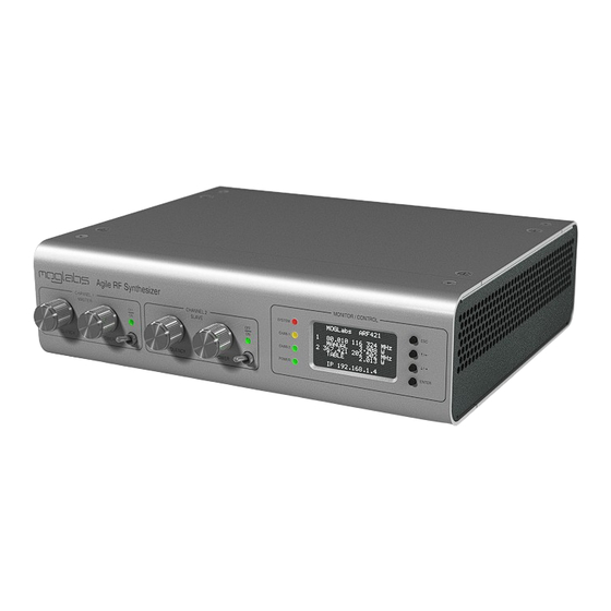
- Page 1 Agile RF Synthesizer & AOM driver ARF021/ARF421, XRF021/XRF421 Version 1.3.0, Rev 2, 3 and 4.
- Page 2 MOGL abs. Contact For further information, please contact: MOG Laboratories P/L MOGLabs USA LLC MOGLabs Europe Suites 34–35 419 14th St Goethepark 9 49 University St Huntingdon PA 16652 10627 Berlin...
- Page 3 We hope that you enjoy using the ARF/XRF , and please let us know if you have any suggestions for improvement in the ARF/XRF or in this document, so that we can make life in the lab better for all. MOGL abs, Melbourne, Australia www.moglabs.com...
-
Page 5: Safety Precautions
Safety Precautions Safe and effective use of this product is very important. Please read the following safety information before attempting to operate. Also please note several specific and unusual cautionary notes before using the MOGL ARF/XRF , in addition to the safety precautions that are standard for any electronic equipment. -
Page 6: Protection Features
Protection Features MOGL ARF/XRF includes a number of features to protect you and your device. Open/short circuit Each output should be connected to a 50 Ω load. The will disable each high-power output if not connected F/XRF or if a short-circuit is detected. Reflected power The reflected power and VSWR (voltage standing wave ratio) are monitored and... -
Page 7: Table Of Contents
Contents Preface Safety Precautions Protection Features 1 Introduction 1.1 Operating modes ..... on/off control ..... 2 Connections and controls 2.1 Front panel controls . - Page 8 Contents 5.3 Dual modulation: fast and slow modes ..5.4 Examples ......6 PID stabilisation 6.1 Signal conditioning .
- Page 9 Contents 9.9 Additional examples ....A Specifications B Firmware upgrades B.1 Firmware components ....B.2 Factory reset .
- Page 10 Contents viii...
-
Page 11: Introduction
1. Introduction MOGL ARF/XRF consists of two independent AD9910 direct digital synthesizer (DDS) sources, each with 4 W amplifier. The frequency, amplitude and phase of each output is software-controlled via a microcontroller and FPGA (field programmable gate array). This enables direct control of the frequency, amplitude and phase of the signals, which can be adjusted in real-time using the front-panel control knobs, or via a scripting language over ethernet or . -
Page 12: Operating Modes
Chapter 1. Introduction then further amplified with a GaN hybrid high-power output stage only). The signals are monitored to check output ARF421/XRF421 power and to measure the reflection ( VSWR chips are controlled by the FPGA . A microcontroller provides external interface with TCPIP communications, and controls... -
Page 13: Advanced Mode
1.1 Operating modes : Basic mode Default state on power-up. In this mode, each channel acts as a simple single-frequency source, with the chips controlled directly by the FPGA . The frequency and power of the signal can be controlled via the front panel, using simple instructions over the FREQ computer interface (e.g. -
Page 14: Rf On/Off Control
Chapter 1. Introduction on/off control output can be turned on and off via software control of the generators (through the command), but for many applica- tions that is too slow, and the extinction ratio is inadequate. The ARF/XRF has additional hardware-based on/off control on the output of each , using an switch before the amplifiers. -
Page 15: Connections And Controls
2. Connections and controls 2.1 Front panel controls Agile RF Synthesizer STATUS CHANNEL 1 CHANNEL 2 CHAN 1 STATUS STATUS CHAN 2 POWER FREQUENCY POWER FREQUENCY POWER Frequency The frequency encoder can be used to adjust the frequency for each channel, when operating in mode. -
Page 16: Front Panel Display/Monitor
Chapter 2. Connections and controls 2.2 Front panel display/monitor display shows key information including frequency and power for each channel, and ethernet information. STATUS Indicator displaying the status of the microcontroller. • Blinking green: Normal operation, no faults • Green/blue: Normal operation, device is initialising •... -
Page 17: Rear Panel Controls And Connections
2.3 Rear panel controls and connections 2.3 Rear panel controls and connections RF OUT MOD IN RF OUT 1 RF OUT 2 FREQ 1 FREQ 2 CLK IN MON 1 MON 2 AMP 1 AMP 2 MOD OUT 90–264Vac 47–63Hz WARNING: connectors on the back-panel are surface-mounted to the inside the unit. -
Page 18: Internal Dip Switches
Chapter 2. Connections and controls CLK IN uses a high stability OCX crystal clock, but can also be synchronised to a high-performance external clock (5 MHz to 1 GHz) input via this connector. The input is 50 Ω terminated. The signal should be 1 V p-p, and preferably square-wave. - Page 19 2.4 Internal DIP switches DIP 1 Default . If switched , the unit will start in legacy firmware upload mode. Connect to the device using a web-browser and upload firmware to the microcontroller. It is strongly recommended to use mogrffw to update the firmware as described in Appendix B; this option is only provided as a fallback option in case mogrffw fails.
- Page 20 Chapter 2. Connections and controls...
-
Page 21: Communications
3. Communications can be connected to a computer by or ethernet ( TCPIP The software package mogrf (chapter 4) provides interactive func- tionality, or communications can be integrated into existing control software. Examples of controlling the ARF/XRF in several languages are provided in Appendix D. - Page 22 Chapter 3. Communications > FREQ,1 < 80.00000009 MHz (0x147AE148) > FREQ,3 < ERR: Invalid channel, 3 In the above example, the frequency query provides a value first in MHz as well as the internal setting (called the “frequency tuning word”) as hexadecimal in brackets. It is strongly recommended that all software should wait for this response and check whether it indicates an error before continuing.
-
Page 23: Tcp/Ip
3.2 TCP/IP 3.2 TCP/IP When ethernet is connected, the will attempt to obtain an address by DHCP . If DHCP fails, an internally defined address will be used. In both cases, the address will be shown on the device display (for example, 10.1.1.190:7802), showing the address and port number for communicating with the device. -
Page 24: Usb
Chapter 3. Communications 3.3 USB ARF/XRF can be directly connected to a host computer using a USB cable (type A-male). The device will appear as a Virtual port - a fast serial port that behaves like an connection. RS232 The required STM32 Virtual COM Port Driver (VCP) device driver is available from the... - Page 25 3.3 USB Note that if the port appears in Device Manager with a different name, then the driver was not successfully installed. If this occurs, disconnect the device from the host computer, reinstall the VCP driver, then reconnect the USB cable.
- Page 26 Chapter 3. Communications...
-
Page 27: Mogrf Host Software
4. MOGRF host software The mogrf software package provides a simple user interface to the basic behaviour of ARF/XRF devices, with the ability to issue commands, run scripts, control tables, and apply firmware updates. Please note: The software described in this section is designed to work with the most recent firmware, which may require you to install a firmware update (see Appendix B). -
Page 28: Device Commander
Chapter 4. MOGRF host software address of the unit in the Device address possible to enter the box and connect directly. 4.2 Device commander The Device commander is an interactive terminal for issuing com- mands and queries to your ARF/XRF device and displaying the result (Figure 4.2). -
Page 29: Mogrf Main Window
4.3 MOGRF main window 4.3 MOGRF main window The main window of mogrf is shown below. The two channels are displayed side-by-side, with information and controls that depend on the current operational mode of each channel. Figure 4.3: The main window of mogrf, showing Channel 1 in normal (NSB) mode and Channel 2 in simple table (TSB) mode. -
Page 30: File Menu
Chapter 4. MOGRF host software 4. Channel output can be controlled by enabling only the switch (signal), amplifiers (power) or both (421-series only). 5. Options to enable external control of the channel output connector (see §7.5). using the input on the DB15 6. - Page 31 4.3 MOGRF main window . Note that changing the Static IP only has an settings over effect if is disabled, or if name resolution fails. DHCP DHCP Figure 4.4: Ethernet configuration interface. Note that changing the ethernet settings will require the application to be restarted, and may also require the device to be rebooted.
- Page 32 Chapter 4. MOGRF host software Figure 4.5: Modulation settings interface, showing that simultaneous FM and AM is enabled on Channel 1, with high bandwidth on AM. PID is disabled but constants have been set. Upload settings Restore previously downloaded settings to the unit. 4.3.3 Help Diagnostics Queries the unit for diagnostic information, which may be useful in...
-
Page 33: Table Viewer
4.4 Table viewer Figure 4.6: Diagnostic information about the connected unit, which should be sent to MOGLabs for analysis if there is a problem with the device. 4.4 Table viewer mode), mogrf provides a viewer for in- In simple table mode (... -
Page 34: External I/O Settings
Chapter 4. MOGRF host software Figure 4.7: Table viewer showing how the frequency, power and phase of a table stored in FLASH memory change across the sequence (left). The example shown is a chirped Gaussian pulse, with a number of rapid on/off pulses at the beginning. - Page 35 4.5 External I/O settings Features of the EXTIO configuration window (Figure 4.8) are: 1. Current state of the input pins of the DB15 connector (note that is disabled on units). 2. Options treat the input on the DB15 connector as an in- terlock (“Latch”...
- Page 36 Chapter 4. MOGRF host software...
-
Page 37: External Modulation
5. External modulation ARF/XRF supports external modulation of the through the modulation input connectors on the back-panel. Frequency, amplitude and phase modulation of the are supported, and dual- modulation is possible for simultaneous FM/AM or FM/PM. WARNING: The modulation inputs are nominally ±1V, and can be permanently damaged by applying higher voltages. -
Page 38: Modulation Gain
Chapter 5. External modulation 5.2 Modulation gain The modulation gain, which controls the modulation depth, is set GAIN using the command. The gain is specified as a signed 32-bit integer (default 0), in either decimal or hexadecimal, with a negative value inverting the modulation action Note: Frequency modulation was changed in firmware v1.3.x to allow finer FM... -
Page 39: Dual Modulation: Fast And Slow Modes
5.3 Dual modulation: fast and slow modes (*): This expression assumes a 50 Ω load, and depends on the indi- vidual unit power calibration. The actual output amplitude respects LIMIT the maximum power limit set by the command. The available modulation depth depends on the difference between the current LIMIT output power (... -
Page 40: Examples
Chapter 5. External modulation Command FM/PM bandwidth AM bandwidth FMSPEED,1,FAST 10 MHz 1 MHz FMSPEED,1,SLOW 1 MHz 10 MHz Table 5.2: Effect of using FMSPEED to control modulation on Channel 1. fast (parallel) mode, and < 3 s in slow (serial) mode. Furthermore, inducing a step change with slow modulation (e.g. - Page 41 5.4 Examples Figure 5.1: Demonstration of simultaneous AM/FM modulated (red) when the modulation inputs are driven by the SLHRAMP monitor output (blue). Figure 5.2: Demonstration of high gain amplitude modulation showing LIMIT clipping at zero and the power limit set by the command.
- Page 42 Chapter 5. External modulation 5.4.2 Comparison of fast and slow modulation The example here shows the same amplitude-modulated waveform FMSPEED using a 1 V sine wave at 100 kHz. When is set to FAST , the amplitude is modulated using the slow serial interface and the enve- FMSPEED lope displays large stepwise discretisation.
-
Page 43: Phase Modulation
5.4 Examples 5.4.3 Phase modulation In some applications, it is desirable to phase modulate one of the channels by ±π, and use the other channel to demodulate the re- sulting signal using a double-balanced mixer. This is achieved with a 2 Vpp modulation input with gain 0x7fff, or a 1 Vpp modulation input with gain 0xffff (Figure 5.4). - Page 44 Chapter 5. External modulation...
-
Page 45: Pid Stabilisation
6. PID stabilisation In addition to external modulation, the ARF/XRF also implements control loops which can be used in conjunction with an perform intensity or frequency stabilisation of a laser. Each channel has an independent controller, which acts to drive an “error signal”... -
Page 46: Pid Control Loop
Chapter 6. PID stabilisation of the controller, it is often necessary to apply analog gain to the error signal to make use of the full dynamic range of the Such signal processing must be done externally to the ARF/XRF , with bandwidth at least an order of magnitude greater than the desired effective bandwidth of amplitude stabilisation. -
Page 47: Dual Modulation With Pid
6.3 Dual modulation with PID When optimising a control loop, it should be kept in mind that the achievable loop bandwidth is limited by the propagation delay of the entire signal processing chain, not just the modulation bandwidth. This includes the impulse response of the , photodetector and signal-processing electronics, as well as the ARF/XRF... -
Page 48: Noise-Eater Implementation
Chapter 6. PID stabilisation 6.4 Noise-eater implementation A common application for controllers is optical noise eating, which technical noise arising from power fluctuations in a laser beam. Figure 6.1 shows a typical configuration, where the intensity of the undiffracted (zero-order) beam is stabilised as seen in Figure 6.2. In this configuration, the acts as a high-speed variable optical attenuator, diffracting some of the light into the unused first-order... -
Page 49: Example
6.5 Example measured optical power. If the measured power is too high, the power is increased and more light is diverted into the diffracted out- put. This allows fluctuations in intensity to be suppressed, at the expense of reducing the transmitted power slightly (typically 90% transmission is achieved). - Page 50 Chapter 6. PID stabilisation...
-
Page 51: Digital I/O
7. Digital I/O digital inputs and outputs (0-5 V) are provided on the ARF/XRF through the DB15 connector on the rear panel, and the high-speed bus ( ). The inputs can be used as triggers and the outputs can be controlled manually or using by table mode entries (§8.3). Note: Digital inputs are pulled high, meaning that a disconnected input pin is equivalent to supplying a high to that input. - Page 52 Chapter 7. Digital I/O Signal Type CH1 OFF TTL in CH1 ON TTL in CH1 SEQ(*) TTL in CH1 DOUT TTL out CH2 SEQ(*) TTL in CH2 ON TTL in CH2 OFF TTL in CH2 DOUT TTL out ±2 5 V CH1 AOUT ±2 5 V CH2 AOUT...
-
Page 53: High-Speed Digital
7.2 High-speed digital CHx-ON Pin 2 (Ch1), Pin 6 (Ch2) Driving this pin LOW in to switch ON mode instructs the FPGA signal (but not the amplifiers). Should be used in combination OFF,ch,SIG with . Has no effect if the signal is already enabled. -
Page 54: Configuration
Chapter 7. Digital I/O Signal Signal Signal 3.3 V 3.3 V 3.3 V Figure 7.2: High-speed digital IO connector (internal). is a 74LVT2244 , output only) or 74LVTH2245 R 3+ , input or output). R 3+ devices, the FPGA can be configured to treat each of the two banks of eight signals as either a bank of inputs or a bank of EXTIO,MODE outputs using the... - Page 55 7.3 Configuration pins. Pins in the high-speed bus can be addressed individually (HSn) or collectively as a whole bank (HSBANK) in case multiple outputs need to be changed simultaneously. HSB is short-hand for HSBANK. Function ON/SEQ DOUT Enable Disable Reset Mode Control Write...
-
Page 56: Ttl Switching
Chapter 7. Digital I/O them in table mode. If and the bank is not in write mode, the bank is changed to write mode first. EXTIO,WRITE EXTIO,WRITE,ch,pin,value value value Write the specified to the output . If , then is an 8-bit number, whose bits correspond to the values to set on value the pins of that bank. - Page 57 7.4 TTL switching allow the output to be switched with minimal delay. The two relevant inputs are labelled (see 7.1). Both of these CHx-OFF CHx-ON inputs are active , and have the following behaviour: CHx-ON When the output is turned , pulling this pin will switch the output...
-
Page 58: External Switching Timing
Chapter 7. Digital I/O 7.5 External switching timing Note: Some units may require a minor hardware modification to achieve the performance described in this section. Please contact abs if you are inter- MOGL ested in performing this modification. There are several approaches to generating pulses using an ARF/XRF mode (normal operation): using the inputs on the... - Page 59 7.5 External switching timing Figure 7.3: Modulation of output using the CHx-OFF input. Green is signal at the source; blue is the signal at the switch (internal ); magenta is the signal. Figure 7.4: Example of pulse generation using the CHx-OFF input.
-
Page 60: Counters
Chapter 7. Digital I/O 7.6 Counters Fast digital counters can be accessed for each digital input pin. devices can use these counters in advanced table mode (§9.4); devices can only use them manually in scripts. To use a counter, the associated pin must be in READ mode and the counter function activated. -
Page 61: Examples
7.7 Examples 7.7 Examples The following examples demonstrate how to configure and use the external I/O pins. Note that pins must be set to MANUAL using the EXTIO,CTRL command to be used for READ WRITE These commands may be useful in executing scripts or diagnosing experiments. - Page 62 Chapter 7. Digital I/O...
-
Page 63: Simple Table Mode
8. Simple table mode Table mode performs sequential execution of up to 8191 instruc- tions with precise timing. This enables generation of complicated pulse sequences, custom envelope shapes, and automated control of experiment sequences through digital I/O. There are two versions of table mode: simple table mode ( mode) serial interface, and advanced table mode which utilises the... -
Page 64: Defining Table Entries
Chapter 8. Simple table mode The phase-accumulator of the is then reset and the table exe- cutes autonomously under control. This provides a very high FPGA degree of reproducibility in terms of both timing of instructions and output of the generators, as the phase accumulator is reset for every execution. - Page 65 8.2 Defining table entries freq Frequency to output during this step Output power during this step phas Phase of the for this step Duration of this step (discretised at 1 us) flags A comma-separated list of flags, comprised of the following: Switch off...
- Page 66 final instruction that sets the output power to minimum. # Example of table output MODE,1,TSB # Begin table TABLE,ENTRY,1,1,100MHz,-10dBm,0,100 TABLE,ENTRY,1,2,100MHz,0dBm,0,100 TABLE,ENTRY,1,3,80MHz,-5dBm,0,100 TABLE,ENTRY,1,4,80MHz,-15.0dBm,0,100 TABLE,ENTRY,1,5,100MHz,-2.0dBm,0,100 TABLE,ENTRY,1,6,100MHz,0x0C00,0,100 TABLE,ENTRY,1,7,100MHz,0x0200,0,100 TABLE,ENTRY,1,8,100MHz,0x001,0,100 TABLE,ENTRIES,1,8 TABLE,START,1 Listing 8.1: Simple table mode demonstration. Figure 8.1: Demonstration of Listing 8.1 on an ARF021...
-
Page 67: Digital I/O
8.3 Digital I/O 8.3 Digital I/O Each entry in the table can control a single digital I/O pin (§8.3.1), or write multiple pins simultaneously (§8.3.2). However, pins must EXTIO be correctly configured using the to be used in table mode: inputs must be set to READ mode, and outputs must be set to... - Page 68 Chapter 8. Simple table mode IO3H Set pin 3 of associated high-speed bank to output HIGH IODT Toggle the output of the associated DOUT pin on the DB15 connector IOA2P Output a short pulse on pin 2 of high-speed bank A IOB1L Set pin 1 of high-speed bank B to output digital The example below shows how to toggle an output in the high-speed...
- Page 69 8.3 Digital I/O Figure 8.2: Example of table mode, showing changing output (blue, lower trace) and synchronised output (red, upper trace) generated by the example in Listing 8.2. bit corresponds to a pin of the high-speed output banks. If a bit is IOMASK IOSET set in the...
- Page 70 Chapter 8. Simple table mode outputs are written at once. Care must be taken when running two tables simultaneously to ensure that the same pin isn’t being writ- ten to simultaneously by both tables, which can result in undefined IOMASK0x00FF behaviour.
- Page 71 8.3 Digital I/O TRIGDF DB15 external input (equivalent to The trigger behaviour is to repeat the current instruction until a trigger is received. Thus if the trigger condition is met during the instruction period, execution will not immediately proceed to the next instruction but rather complete the duration of the instruction instruction should be as small as TRIG...
-
Page 72: Loops And Triggers
Chapter 8. Simple table mode Figure 8.3: Demonstration of waiting for a trigger within a table sequence. The second table entry is repeated until a falling edge in the trigger (magenta, top) is detected. The digital output (red, bottom) is toggled several times showing the instruction being repeated. - Page 73 8.4 Loops and triggers condition can be an integer in the range [1 4095], correspond- ing to the number of times to execute the loop, or a hardware de- IOxy scriptor flag of the form , indicating the loop should be repeated until the digital input pin exhibits behaviour , as described below.
- Page 74 Chapter 8. Simple table mode a loop source, a “dummy” instruction is added to the end, which also turns off the TABLE,CLEAR,1 TABLE,ENTRIES,1,4 TABLE,ENTRY,1,1,100MHz,0dBm,0,1us TABLE,ENTRY,1,2,100MHz,-5dBm,0,4us TABLE,ENTRY,1,3,100Mhz,-10dBm,0,2us TABLE,LOOP,1,3,1,4 TABLE,ENTRY,1,4,100MHz,-30dBm,0,1us Listing 8.3: Demonstration of a simple loop Figure 8.4: Demonstration of a simple loop. LOOP An alternate way of specifying the instruction in the above...
-
Page 75: Upload And Download
8.5 Upload and download 8.5 Upload and download The host software mogrf provides convenient functionality that en- ables upload and download of tables in both binary and format. This simplifies handling of tables, and allows simple generation of sequences from scripting languages like matlab or python, and the human-readable structure simplifies trouble-shooting. -
Page 76: Re-Arm And Restart
Chapter 8. Simple table mode 8.6 Re-arm and restart The microcontroller can be instructed to automatically re-arm the TABLE,REARM table after a successful execution using the command. This automatically prepares the table for execution from either hard- ware or software trigger once execution has finished. Furthermore, the table can be repeated continuously by enabling TABLE,RESTART option. -
Page 77: Linear Ramps
8.7 Linear ramps 8.7 Linear ramps It is often desirable to linearly ramp a parameter without having TABLE,RAMP to specify the individual table entries manually. The command provides a convenient way to generate such ramps. TABLE,RAMP TABLE,RAMP,ch,param,start,stop,duration,count param Appends table entries to the channel that linearly ramp start stop... - Page 78 Chapter 8. Simple table mode Figure 8.5: Output generated by Listing 8.7 showing linear ramps in amplitude. The ramp functionality can also be applied to frequency or phase. TABLE,RAMP Listing 8.8 shows how multiple commands can be used to execute a sequence of slow frequency ramps that can be watched on a spectrum analyser.
-
Page 79: Synchronous Table Execution
8.8 Synchronous table execution Time (s) Figure 8.6: Frequency ramps achieved by chaining together RAMPFREQ commands in mode. 8.8 Synchronous table execution When operating both channels in table mode, it is possible to syn- chronise the two channels. This synchronisation occurs both at FPGA level (so that the table entries are stepped through simultaneously), and at the... - Page 80 Chapter 8. Simple table mode Figure 8.7: Example showing the two outputs when executing the same table synchronously on both channels. The remains in phase across table instructions. It is also possible to synchronise the triggers received by the DB15 two tables.
-
Page 81: Advanced Table Mode (Xrf)
9. Advanced table mode (XRF) has access to an advanced table mode with increased func- tionality, flexibility and significantly faster execution than normal ) table mode. Due to the added complexity, it is strongly recom- mended that users be familiar with simple table mode before reading this chapter. -
Page 82: Defining Table Entries
Chapter 9. Advanced table mode (XRF) It should also be noted that the while the outputs can be syn- chronised, the rf components following the introduce a small frequency-dependent propagation delay. However, this delay is fixed for a given frequency, and can be calibrated in applications where it is important. - Page 83 9.2 Defining table entries The listing below demonstrates how to set up advanced table mode to control the envelope (amplitude) of the signal, # enter fast table mode MODE,1,TPA # clear any table entries or settings TABLE,CLEAR,1 # set amplitude (power) as the parallel parameter TABLE,XPARAM,1,POW # define a table TABLE,APPEND,1,POW,5dbm,16ns...
- Page 84 Chapter 9. Advanced table mode (XRF) It is anticipated that many applications will only seek to control a single parameter, in which case only the parallel interface need be used. However, a second command format is provided to simultane- ously set all three parameters using the serial interface. TABLE,ENTRY TABLE,ENTRY,ch,num,freq,pow,phase,duration,flags Defines a serial (...
- Page 85 9.2 Defining table entries # some other instructions while the SIF loads TABLE,APPEND,1,POW,-5dbm,320ns TABLE,APPEND,1,POW,-10dbm,320ns TABLE,APPEND,1,POW,-5dbm,320ns # trigger the serial instruction TABLE,APPEND,1,POW,5dbm,200ns,UPD # another parallel instruction at new frequency TABLE,APPEND,1,POW,-5dbm,100ns # final instruction to power down TABLE,APPEND,1,POW,0x0,0x1 Listing 9.3: Demonstration of parallel instructions during a SIF load Figure 9.2: Output generated by Listing 9.3 Note: The value corresponding to the parallel parameter is ignored when loading a serial update and must be set separately.
-
Page 86: Initial And Final States
Chapter 9. Advanced table mode (XRF) 9.3 Initial and final states TABLE,ARM As in simple table mode, when the command is used to ready the table for execution, the output is enabled and amplifiers switched on (if present). The state of the after arming is therefore the same as the last table instruction that was run. -
Page 87: Counters
9.4 Counters instruction will remain unless subsequently overwritten by one of these commands. It is therefore strongly recommended to specify the initial and final states. 9.4 Counters devices are capable of controlling the digital input counters in advanced table mode, and using the counters as a loop condition. This assists in experiment automation, whereby the execution can be paused until a critical count is received. -
Page 88: Loops And Triggers
Chapter 9. Advanced table mode (XRF) # configure the counter EXTIO,MODE,1,HSB,READ # set bank A into read mode EXTIO,COUNTER,1,HS1,FALLING # set pin A1 to count falling edges # create the table MODE,1,TPA TABLE,CLEAR,1 TABLE,XPARAM,1,POW TABLE,APPEND,1,POW,-5dBm,100ns,CA1S # start the counter TABLE,APPEND,1,POW,0dBm,16ns # accumulate counts TABLE,LOOP,1,-1,0,COUNT,IOA1,1000 # loop until 1000 counts... -
Page 89: Linear Ramps Using Extrapolation
9.6 Linear ramps using extrapolation 9.6 Linear ramps using extrapolation One of the powerful features provided in advanced table mode is the ability to specify linear ramps in parallel mode, which reduces the number of instructions necessary to produce smooth piecewise- linear ramps. - Page 90 Chapter 9. Advanced table mode (XRF) Listing 9.6 demonstrates how to linearly ramp the power in 100 steps using a single instruction instead of 100 individual instructions REPn using the notation. The result is shown in Figure 9.3. TABLE,CLEAR,1 TABLE,XPARAM,1,POW # set power to OFF TABLE,APPEND,1,POW,0x0,0x1 # linear ramp up (100 steps)
-
Page 91: Frequency Gain
9.7 Frequency gain hexadecimal increments. TABLE,CLEAR,1 TABLE,XPARAM,1,POW # define a ramp from off (0x0) to 0dBm TABLE,RAMP,1,POW,0x0,0dBm,16ns,100 # append the reverse of the ramp TABLE,RAMP,1,POW,0dBm,0x0,16ns,100 # loop back to the beginning twice more TABLE,LOOP,1,-1,1,2 # last entry cannot be a loop TABLE,APPEND,1,POW,0x0,16ns Listing 9.7: Alternate specification of triangle wave using TABLE,RAMP. - Page 92 Chapter 9. Advanced table mode (XRF) Gain Step Gain Step 0.23 Hz 7.54 kHz 59.6 Hz 1.95 MHz 0.47 Hz 15.3 kHz 119 Hz 3.91 MHz 0.93 Hz 30.5 kHz 238 Hz 7.81 MHz 1.86 Hz 61.0 kHz 477 Hz 15.6 MHz 3.73 Hz 122 kHz...
-
Page 93: Other Instruction Parameters
9.8 Other instruction parameters 9.8 Other instruction parameters The following parameters can also be specified in parallel table entries, for special behaviours, as listed below. Instructions that use the serial interface must be followed with a subsequent instruction containing the flag to activate them. -
Page 94: Additional Examples
Chapter 9. Advanced table mode (XRF) 9.9 Additional examples 9.9.1 Gaussian envelope The following example demonstrates creation of a short (300 ns) Gaussian pulse by specifying the output power at the maximum up- date rate (instruction duration 0 1 = 16 ns). The resulting output waveform is shown in Figure 9.5. - Page 95 9.9 Additional examples Figure 9.5: Example of a short Gaussian pulse. 9.9.2 Back-to-back pulses with different frequency This example demonstrates how to generate two back-to-back 1 s pulses with different frequencies by loading the second frequency during the first pulse. The feature is used to smooth EXTRAPOLATE the envelope, and the...
- Page 96 Chapter 9. Advanced table mode (XRF) TABLE,APPEND,1,POW,0x0264,0x1,REP3 TABLE,APPEND,1,POW,0x0222,0x1,REP3 TABLE,APPEND,1,POW,0x017b,0x1,REP3 TABLE,APPEND,1,POW,0x0088,0x1,REP3 TABLE,APPEND,1,POW,-0x088,0x1,REP3 TABLE,APPEND,1,POW,-0x17b,0x1,REP3 TABLE,APPEND,1,POW,-0x222,0x1,REP3 TABLE,APPEND,1,POW,-0x264,0x1,REP3 TABLE,APPEND,1,POW,-0x244,0x1,REP3 TABLE,APPEND,1,POW,-0x1db,0x1,REP3 TABLE,APPEND,1,POW,-0x153,0x1,REP3 TABLE,APPEND,1,POW,-0x0d1,0x1,REP3 TABLE,APPEND,1,POW,-0x06a,0x1,REP3 TABLE,APPEND,1,POW,-0x01f,0x1,REP3 # trigger the frequency change TABLE,APPEND,1,HOLD,0x1,UPD # loop back to create second pulse TABLE,LOOP,1,-1,4,1 TABLE,APPEND,1,POW,0x0,0x1 Listing 9.9: Back-to-back shaped pulses with different frequencies Figure 9.6: Two 1 s Gaussian pulses generated in advanced table mode with amplitude on the parallel bus.
- Page 97 9.9 Additional examples 9.9.3 Parallel frequency mode The following example demonstrates control of the frequency with the parallel interface. # set up table mode MODE,1,TPA TABLE,CLEAR,1 # use HSB for triggering EXTIO,CTRL,1,HSB,AUTO # change to FREQ mode and set the FM gain TABLE,XPARAM,1,FREQ,15 # step through a number of frequencies TABLE,APPEND,1,FREQ,20,0x5,IOA1H...
- Page 98 Chapter 9. Advanced table mode (XRF)
-
Page 99: A Specifications
A. Specifications Specification Parameter RF characteristics +36 dBm (+16 dBm) ±1 dBm Output power ARF421 (ARF021) 14-bit resolution 20 to 400 MHz (32-bit resolution) Frequency ◦ ±1 ppm (0 to 50 Frequency stability 0 to 2π (16-bit resolution) Phase <... - Page 100 Appendix A. Specifications Digital input/output (per channel) TTL hardwired, positive logic only RF on/off TTL input to continue table execution Trigger input TTL output on DB15 connector Shutter output 8 x TTL High-speed out 2.2V TTL input high 0.6V TTL input low 7.0V Absolute max in -0.5V...
-
Page 101: B Firmware Upgrades
B. Firmware upgrades From time to time, MOGL abs will release updates to the ARF/XRF firmware, which enable new functionality or address issues in the version which shipped with your device. This section contains in- structions on how to apply firmware updates to your device. The device firmware consists of several components. -
Page 102: Factory Reset
Appendix B. Firmware upgrades B.2 Factory reset If a firmware upgrade fails and the device subsequently cannot boot, a factory reset (rebooting with DIP4 set to ) must be applied. All images will be copied from factory area of to the default (current) area of , and then to the relevant microcontroller flash locations. - Page 103 B.3 Upgrade via mogrffw Figure B.1: The mogrffw firmware update application connected to a unit, showing the serial number (1), model (2) and current firmware versions (3). Note that some values may be unavailable if the device is in “firmware up- date mode”.
-
Page 104: Upgrade Via Web Interface
Appendix B. Firmware upgrades Figure B.2: The mogrffw firmware update application. The versions run- ning on the device are compared against the selected package, in this instance showing that an update is available for the UC (yellow) and the other components are up-to-date (green). 1. - Page 105 4. Use a web browser and connect to the specified IP address. 5. At the prompt, enter your user ID and password. These can be changed in EEPROM , but the factory settings are moglabs UserID: agilerf Password: 6. Select Browse and then select the microcontroller firmware file.
-
Page 106: Upgrading An Arf To An Xrf
Appendix B. Firmware upgrades 11. Once the microcontroller has been upgraded, it will be nec- firmware using mogrffw. If essary to then upgrade the FPGA this is not done, an “ FPGA VERSION ” error will be displayed when the device is rebooted. If you encounter any difficulties, please get in touch with MOGL abs. -
Page 107: C Command Language
Please note: The command language is being continuously updated across firmware releases to improve functionality and add features. When upgrading firmware, please refer to the most recent version of the manual available at http://www.moglabs.com In particular, code written for v0.1-series firmware may need updat- ing to be compatible with the current release;... -
Page 108: General Functions
Appendix C. Command language Calibrations are used to convert parameters to internal discretised values. Most commands will return a message that includes the actual value, which may differ from the requested value because of discretisation and/or parameter limits. If required, internal values can be specified directly using hexadec- imal formatted to include a “0x”... -
Page 109: Primary Rf Control
C.4 Primary control Note: changing operational mode automatically switches off both signal and amplifier of the designated channel. Some options are only available in particular modes, as specified in the commands list. OFF/ON OFF,ch[,mode] ON,ch[,mode] Control output for specified channel. The signal and amplifiers can be individually controlled, which allows for more rapid switching response (see §7.5). - Page 110 Appendix C. Command language POWER POW,ch[,value] modes only. Set channel to specified output power (or amplitude). The output power is computed using a factory calibra- tion, and has 14-bit resolution. Requesting a value higher than the LIMIT limit set with the command results in an error.
-
Page 111: Modulation
C.5 Modulation SINCFILTER SINC,ch[,onoff] Activate or deactivate the internal sinc filter of the for the AD9910 selected channel. Enabling sinc filter improves the frequency re- sponse of the but reduces output power by approximately 3 dB. More details can be found in the datasheet regarding the AD9910 CFR1... -
Page 112: Digital Ramp Generator
Appendix C. Command language gain given channel. is a 32-bit signed integer that controls the gain depth of the modulation (§5.2). If is 0 then the modulation gain is disabled, and if is negative then the modulation action is inverted. FMSPEED FMSPEED,ch[,speed] Controls the bandwidth of frequency/phase modulation for the given... - Page 113 C.6 Digital ramp generator EXT, HW waits for a hardware trigger on the CHx-OFF pin before executing the to ramp. AUTO, CONT Execute the ramp continuously; once a ramp is completed it will reset and execute again. The ramp begins immediately after the command is issued.
-
Page 114: Monitor Outputs
Appendix C. Command language C.7 Monitor outputs A number of monitoring waveforms can be output for testing and diagnostic purposes, including monitoring of the output powers and the PID loop. MOUT MOUT[,ch][,type] type Sets the monitor output to , which is one of the options listed below. - Page 115 C.8 Clock reference An external reference can be used to replace the on-board 20 MHz oscillator, via the rear panel input to permit synchronisa- CLK IN tion with other devices. A wide variety of clock sources can be used, including standard 10 MHz references derived from signals or CLKSRC atomic clocks, as set using the...
-
Page 116: C.9 Table Mode
Appendix C. Command language C.9 Table mode Table mode gives access to the powerful sequencing functionality of the devices, as detailed in chapter 8. devices also have access to advanced table mode (chapter 9) using the same com- mands. Note that both the command structure and internal binary representation of tables was changed in firmware v1.3.0, so binary tables from previous versions cannot be used directly. - Page 117 C.9 Table mode ENTRIES TABLE,ENTRIES,ch[,num] Defines the last table entry number for the given channel. Failing to correctly set the number of entries can result in undefined behaviour. LENGTH TABLE,ENTRIES A synonym for ENTRY TABLE,ENTRY,ch,num[,freq,ampl,phase,duration][,flags] Sets (or returns) the currently loaded table entry of channel Entry numbers start at 1 and tables can contain up to 8191 entries.
-
Page 118: Pid Feedback
Appendix C. Command language LOAD TABLE,LOAD,ch,slot Loads the table from the specified slot in memory to the FLASH designated channel. DUMP TABLE,DUMP,ch Prints the table for the specified channel in binary for later upload. The command should not be used from an interactive terminal and is provided for automation purposes. - Page 119 C.10 PID feedback DISABLE PID,DISABLE,ch Disables the controller for the given channel. RATE PID,RATE,ch[,rate] rate rate Sets the at which the analogue control signal is digitised. is a floating point value in MHz, which is rounded to the nearest valid rate. Valid rates are 15.6 MHz, 7.81 MHz, 3.91 MHz and 1.95 MHz.
-
Page 120: External Io Functions
Appendix C. Command language C.11 External IO functions Controls the behaviour of the digital lines on the DB15 and 30-pin high-speed connectors as described in chapter 7. Note the high- speed banks on devices are output-only. EXTIO,fn,ch,pin,[parameters] Command structure: ENABLE Enables the main or default function of the pin. - Page 121 C.11 External IO functions mode , then must be one of READ Configure the 8 pins of the bank for input ( R 3+ only). WRITE Configure the 8 pins of the bank for output. This command does not apply to any other pins. CONTROL Sets or returns the current control mechanism for the specified pin.
-
Page 122: Configuration Settings
Appendix C. Command language C.12 Configuration settings SET, GET Set and report EEPROM configuration values. Each command described below has a corresponding command to report the relevant parameter. ipaddr SET,ipaddr,"xxx.xxx.xxx.xxx" address based on decimal dotted-quad string (for example ”10.1.1.180”). Note that the double-quotes are part of the syntax and must be included to delimit the address string. - Page 123 C.13 Direct DDS control WARNING: Using these commands bypasses all safeguards and can result in unde- fined behaviour or damage to connected devices. Their use is intended for advanced users only, in close consultation with the AD9910 datasheet. PROFILE PROFILE,ch,frequency,amplitude,phase Define the frequency, amplitude and phase for profile of the specified channel.
- Page 124 Appendix C. Command language SYNC Multichip sync (32-bit) RLIM Digital ramp limit (64-bit) RSTP Digital ramp step size (64-bit) RRTE Digital ramp rate (32-bit) STP[0-7] Single tone profile 0-7 (64-bit) RAMW RAM word register (32-bit) DINIT DINIT,ch Executes the startup initialisation script for the given channel. The command allows a re-initialisation of the control registers to their boot-time defaults, which is useful in...
-
Page 125: D Code Examples
D.1 python Communication is handled by a “device” class, which provides con- venience functions for sending commands and queries. # ARF python example, (c) MOGLabs 2016 from mogdevice import MOGDevice # connect to the device dev = MOGDevice(’10.1.1.23’) # print some information print ’Device info:’, dev.ask(’info’) - Page 126 Appendix D. Code examples # ARF Gaussian pulse example, (c) MOGLabs 2016 from mogdevice import MOGDevice import numpy as np # connect to the device dev = MOGDevice(’10.1.1.45’) print ’Device info:’, dev.ask(’info’) # construct the pulse N = 200 X = np.linspace(-2,2,N) Y = 30*(np.exp(-X**2)-1)
-
Page 127: Matlab
ARF/XRF how to create a simple table that produces a pulse with a Gaussian envelope. %%%%%%%%%%%%%%%%%%%%%%%%%%%%%%%%%%%%%%%%%%%%%%%%%%% % ARF MATLAB example, (c) MOGLabs 2017 %%%%%%%%%%%%%%%%%%%%%%%%%%%%%%%%%%%%%%%%%%%%%%%%%%% % create a device instance dev = mogdevice(); % example: connecting by ethernet dev.connect(’10.1.1.31’);... -
Page 128: Labview
Appendix D. Code examples D.3 LabVIEW The LabVIEW drivers provided make use of NI-VISA to provide a unified interface over both ethernet and . They perform automatic error checking, and are compatible with LabVIEW-2009 and later editions. Figure D.2: Example LabVIEW program that connects to an ARF unit, and performs a number of queries When using these drivers, it is strongly recommended that the au- tomatic session close option be enabled, to prevent communications... - Page 130 2015, 2016, 2017 MOG Laboratories Pty Ltd Suites 34–35, 49 University St, Carlton, VIC 3053 Australia Product specifications and descriptions in this doc- Tel: +61 3 9939 0677 info@moglabs.com ument are subject to change without notice.
Need help?
Do you have a question about the ARF021 and is the answer not in the manual?
Questions and answers