Table of Contents
Advertisement
Available languages
Available languages
Quick Links
Advertisement
Chapters
Table of Contents

Subscribe to Our Youtube Channel
Related Manuals for KNOVA KN CP-2042B

Summary of Contents for KNOVA KN CP-2042B
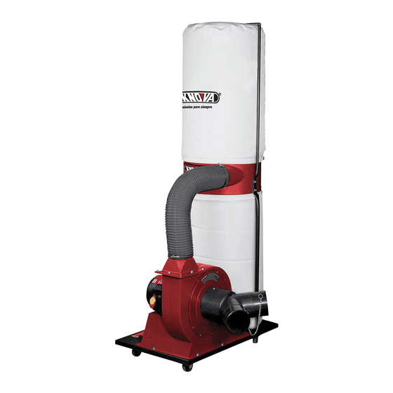
- Page 1 Dust collector Colector de polvo KN CP-2042B...
-
Page 2: Table Of Contents
TECHNICAL DATA MODEL KN CP-2042B Motor: 2 HP. 240 V. 60 Hz. Bag apacity (2): 42 gallon Base size: 33-1/2”... -
Page 3: Safety Rules For Working Equipment
ADDITIONAL SAFETY RULES FOR DUST COLLECTOR • Connect to properly, grounded outlet only • Keep hair, loose clothing, fingers, and all parts of body away (See “Grounding instructions” on page 11) from openings and moving parts. Save these instructions • Extension cords in poor condition or that are too small can pose fire and shock hazards. -
Page 4: Loose Parts Bag
LOOSE PARTS BAG Allen wrench: Ø 5 mm ..........1 piece SWITCH WIRING DIAGRAM Open end wrench 10 x 12 ......... 1 piece ø 1 POWER SWITCH WIRING Toggle switch Motor wire On / Off switch 1 ø 3 ø Black Black Groundig... -
Page 5: Grounding
MOTOR CONTROL adaptor should only be used until a properly grounded outlet can be installed by qualified electrician. The three coloured rigid ear plug extending from the adapter, must be connected to a permanent ground such as a properly grounded outlet box. Note: The type of electrical plug and receptacle differs from country to country Caution: In Canada, only the grounding shown in figure (A) -
Page 6: Assembly
ASSEMBLY 1. To assemble, first place the base plate upside down. Then attach the four casters to the plate using the holes provided and tighten with the wrench. Fig. 4 Fig. 1 4. The collector support can now be mounted to the base plate as shown in figure 5. - Page 7 ASSEMBLY 5. Attach the collector (C) to the two collector supports, 7. Now attach one making sure the side hole is facing the collector body end the hose (a) as shown in figure 6. to the collector body and the other end to the side hole of the collector.
- Page 8 ASSEMBLY 12. Install the inlet shutter to the collector fan / motor 9. Place the collector and filter bags (h) onto the collector assembly using a 3/16” pan flange head screw. and secure with the belts as shown in figure 11. Tighten with a screwdriver, as shown in figure 13.1.
-
Page 9: Maintenance
MAINTENANCE WARNING Build up of dust in motor can cause motor damage. Periodic Always disconnect the dust collector cleaning of motor is not only recommended, but mandatory from the power source before commencing any for normal performance of the dust collector. maintenance. -
Page 10: Diagram Of Dust Collector Parts
EXPLODED DIAGRAM OF DUST COLLECTOR PARTS... -
Page 11: Parts List
PARTS LIST Specification Part No. D e s c r i p t i o n Q’ty. Part No. D e s c r i p t i o n Specification Q’ty. Caster 5/16”-18 UNC Screw hex flange head 5/16” – 18UNC x 1/2” 32 Outlet Base plate Hose clamp... -
Page 12: Tabla De Contenido
DATOS TECNICOS MODEL KN CP-2042B Motor: 2 HP. 240 V. 60 Hz. Cap. de bolsas (2): 5.7 pies cúbicos c/u Dim. -
Page 13: Reglas De Seguridad Para Trabajar Maquinaria
REGLAS DE SEGURIDAD ADICIONALES PARA COLECTORES DE POLVO • No manipule la clavija del sistema colector de polvo con • Las extensiones eléctricas en malas condiciones o que son las manos mojadas. muy pequeñas pueden causar riesgos de fuego o choques eléctricos. -
Page 14: Cableado Del Interruptor
BOLSA DE PIEZAS SUELTAS Llave allen: Ø 5 mm ..........1 pieza DIAGRAMA DE CABLEADO DEL INTERRUPTOR Llave española 10 x 12 ..........1 pieza ø 1 CABLEADO DEL INTERRUPTOR Interruptor de palanca Cable de motor Interruptor de botones 1 ø 3 ø... -
Page 15: Diagrama De Partes
DIAGRAMA DE PARTES Encendido Clavija de Tapa de caja puesta a tierra de salida a tierra Adaptador Terminal de Clavija de puesta a tierra puesta a tierra Apagado DIMESIONES DE LOS CONECTORES DE ENTRADA Y SALIDA ATERRIZAJE Salida de Ø 5” 1. -
Page 16: Ensablado
ENSAMBLADO 1. Para ensamblar, primero voltee la placa base. Luego instale las cuatro ruedas a la base usando los orificios provistos y apriete con la llave. Fig. 4 Fig. 1 4. Ahora puede montar el soporte del colector a la placa base como se muestra en la Fig. - Page 17 ENSAMBLADO 5. Una el colector (C) a los dos soportes de colector 7. Ahora una un verificando que el orificio lateral quede hacia el cuerpo extremo de la del colector como se muestra en la Fig. 6 manguera (a) al cuerpo del colector y el otro extremo al orificio...
- Page 18 EMSAMBLADO 9. Coloque las bolsas colectoras y de filtro (h) en el colector 12. Install 12. Instale el divisor de entrada en el ensamblaje de ventilador/motor usando un tornillo 3/16”. Apriete con un y asegúrelas con las bandas como se muestra en la Fig. 11 destornillador como se muestra en la Fig.
-
Page 19: Mantenimiento
MANTENIMIENTO ADVERTENCIA La acumulación de polvo en el motor puede causar daños al Siempre desconecte el colector de mismo. La limpieza periódica del motor no sólo se recomienda polvo de la corriente eléctrica antes de empezar sino que es obligatoria para un desempeño adecuado del cualquier mantenimiento colector de polvo. -
Page 20: Diagrama De Partes Del Colector De Polvo
DIAGRAMA DE PARTES DEL COLECTOR DE POLVO... -
Page 21: Lista De Partes
LISTA DE PARTES Especificación Part No. D e s c r i p c i ó n Cant. Part No. D e s c r i p t i o n Specification Q’ty. Rueda Tuerca 5/16”-18 UNC Tornillo 5/16” – 18UNC x 1/2” 32 salida Placa base Abrazadera de manguera... - Page 22 www.knova.com.mx...
Need help?
Do you have a question about the KN CP-2042B and is the answer not in the manual?
Questions and answers