Advertisement
Quick Links
Advertisement

Subscribe to Our Youtube Channel
Related Manuals for peerless-AV SC590


Summary of Contents for peerless-AV SC590
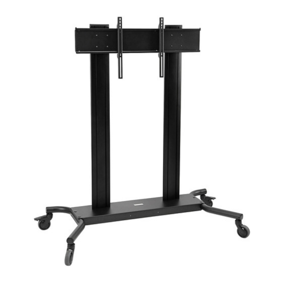
- Page 1 Installation and Assembly: Flat Panel Display Cart Models: SC590, SC590-S ACC964 (sold separately) Max Load Capacity: 300 lb (136.1 kg) 2300 White Oak Circle • Aurora, Il 60502 • (800) 865-2112 • Fax: (800) 359-6500 • www.peerless-av.com ISSUED: 08-08-12 SHEET #: 009-9074-1...
-
Page 2: Tools Needed For Assembly
NOTE: Read entire instruction sheet before you start installation and assembly. WARNING • Do not begin to install your Peerless product until you have read and understood the instructions and warnings contained in this Installation Sheet. If you have any questions regarding any of the instructions or warnings, for US customers please call Peerless customer care at 1-800-865-2112, for all international customers, please contact your local distributor. -
Page 3: Parts List
Before you begin, make sure all parts shown are included with your product. Parts List SC590 SC590-S Description Qty. Part Number Part Number mount bracket 201-1156 201-G4156 hook plate 201-1157 201-G4157 M10 x .402 ID lock washer 540-9424 540-9424 base... - Page 4 Parts may appear slightly different than illustrated. Parts List continued Security Tilt Bracket Fasteners M4 x 12mm (6) M4 x 25mm (4) M5 x 12mm (4) M5 x 25mm (4) M6 x 12mm (4) (510-1079) (510-1082) (520-1064) (520-1122) (520-1050) .75" spacer (540-1059) (4) M6 x 20mm (4) M6 x 25mm (4)
- Page 5 Insert right leg (R) into base housing (D) as shown in fi g. 1.1. Then align holes in right leg with holes in base housing (D). Fasten base housing to right leg using two 3/8-16 x 1.5" bolts (W) and two joint connectors (V). NOTE: Left and right legs can be identifi...
- Page 6 Attach uprights (G) to base (D), as shown below using six 3/8-16 x 2.5" socket screws (L) and M10 x .402ID lock washers (C). Tighten all screws. fi g. 3.1 Loosely attach six 1/4-20 x 12 mm screws (I) and Slide mount bracket (A) onto upright (G) so that 1/4- 1/4-20 nuts (J) to mount bracket (A).
- Page 7 Snap top cover (H) onto upright (G). Insert two 1/4-20 x 12 mm screws (I) into mount bracket (A), leaving 3/16" of exposed thread as shown in fi gure 7.1 and detail 2. fi g. 7.1 3/16" DETAIL 2 Attaching Universal Adapter Plate Attach one universal plate (E) to two hook plates Attach hook plate (B) to mount bracket (A).
- Page 8 Insert two 1/4-20 x 12 mm screws (I) into holes indicated below for desired display orientation. Tighten all screws using 4 mm allen wrench (Q). No Tilt 2° Backward Tilt 5° Forward Tilt 8 of 12 ISSUED: 08-08-12 SHEET #: 009-9074-1...
-
Page 9: Installing Adapter Brackets
Installing Adapter Brackets WARNING • Tighten screws so adapter brackets are fi rmly attached. Do not tighten with excessive force. Overtightening can cause stress damage to screws, greatly reducing their holding power and possibly causing screw heads to become detached. Tighten to 40 in. • lb (4.5 N.M.) maximum torque. •... - Page 10 For Flat Back Display Begin with the shortest length screw, hand thread through multi-washer and adapter bracket (F) into display as 11-1 shown below. Screw must make at least three full turns into the mounting hole and fi t snug into place. Do not over tighten.
- Page 11 Mounting and Removing Flat Panel Display WARNING • Always use an assistant or mechanical lifting equipment to safely lift and position the fl at panel display. Hook adapter brackets (F) onto universal plate (E), then slowly swing display in as shown. Turn safety screws, using security allen wrench (Q), clockwise at least six times to prevent display from being removed as shown in detail 3.
-
Page 12: Limited Five-Year Warranty
Limited Warranty or impose any obligation on Peerless in connection with the sale of any Peerless® product. This warranty gives specifi c legal rights, and you may also have other rights which vary from state to state. www.peerless-av.com © 2012 Peerless Industries, Inc.
Need help?
Do you have a question about the SC590 and is the answer not in the manual?
Questions and answers