ETNA Hydropan Single with Alarm Kit Operation And Maintenance Manual
Hide thumbs
Also See for Hydropan Single with Alarm Kit:
- Operation and maintenance manual (12 pages) ,
- Operation and maintenance manual (16 pages)
Advertisement
Advertisement
Table of Contents

Related Manuals for ETNA Hydropan Single with Alarm Kit


Summary of Contents for ETNA Hydropan Single with Alarm Kit
- Page 1 Hydropan Single with Alarm Kit Operation and Maintenance Manual...
-
Page 2: Product Information
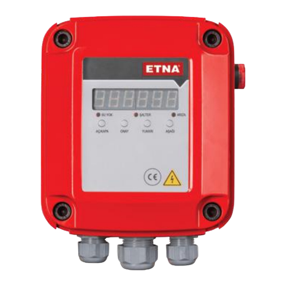
1. Product Information Hydropan-Single Control Panel is used to control , display modes and faults of single pump booster systems, has 7 segment display and uniquely designed electronic main board. In addition to the electronic board and 7 segment display, the panel also has No Water / Pressure Switch / Fault warning leds as well as Up / Down buttons used to surf in menus , Approval button to confirm parameter changes and ON / OFF button . - Page 3 7 Segment Display Current Transformers Connection Cable Power Relays Voltage Transformer Connectors Earth Connection Bar Cable Glands Figure 2. Hydropan Single Internal View www.etna.com.tr...
-
Page 4: Technical Specifications
2. Technical Specifications • Compatible with booster, deep well and waste water applications • User friendly interface • 8 bit microcontroller based design tabanlı tasarım • 7 Segment display • 3 phase voltage measurement and display on screen • High Voltage Protection Setting •... - Page 5 “Down” button for once when display is on main screen. It is possible to enter the submenu by Figure 6. Low Voltage Setting Menu re-pressing the “Approval” button and low voltage protection value can be set by using “Up/Down” buttons. www.etna.com.tr...
- Page 6 c. High Current Protection Setting Menu High Current Protection Setting Menu can be reached by pressing “Approval” button first and then “Down” button for two times when display is on main screen. It is possible to enter the submenu Figure 7. High Current Settings Menu Menu by re-pressing the “Approval”...
-
Page 7: Maintenance
Please cut the power supply before performing any intervention. • Check and make sure that there is no loose connections on power supply and earth connection • Check and make sure that there is no damage , hole or color change caused by overheating on cables. www.etna.com.tr... -
Page 8: Troubleshooting
6. Troubleshooting ERROR CODE FAULT ACTION ERROR 1 HIGH • Check power supply input value VOLTAGE • Check high voltage protection value as parameter P1 FAULT ERROR 2 • Check power supply input value VOLTAGE • Check low voltage protection value as parameter P2 FAULT •... - Page 9 30A Relay 30A Relay 30A Relay TRANSFORMER TRANSFORMER 30A Relay 30A Relay N L1 N L1 MOTOR POWER MOTOR POWER WELL POWER SUPPLY POWER SUPPLY Figure 15. SINGLE PHASE Figure 14. SINGLE PHASE Deep Well Mode Connection Booster Mode Connection www.etna.com.tr...
- Page 10 Dudullu Organize Sanayi Bölgesi 2. Cadde No: 14 34775 Ümraniye İstanbul / Turkey Tel : +90 216 561 47 74 (Pbx) • Fax : +90 216 561 47 50 www.etna.com.tr/en • info@etna.com.tr customer service...
Need help?
Do you have a question about the Hydropan Single with Alarm Kit and is the answer not in the manual?
Questions and answers