ETNA Hydropan Operation And Maintenance Manual
Hide thumbs
Also See for Hydropan:
- Operation and maintenance manual (12 pages) ,
- Operation and maintenance manual (10 pages) ,
- Operation and maintenance manual (40 pages)
Table of Contents
Advertisement
Quick Links
Advertisement
Table of Contents

Related Manuals for ETNA Hydropan


Summary of Contents for ETNA Hydropan
- Page 1 Hydropan Operation and Maintenance Manual...
-
Page 2: Product Information
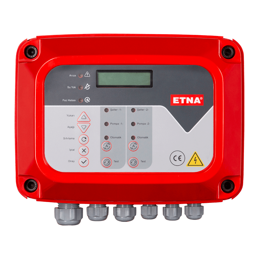
1. Product Information ETNA Control Panel is used to control and display modes, faults of two pump booster systems, has 2*16 character LCD display and uniquely designed electronic main board and display module. The panel has General Fault / No Water / Phase Fault warning leds, Up /... - Page 3 Power Relays Current Transformers Voltage Transformer Circuit Breaker Connectors Cable Gland Earth Connection Bar Figure 2. Control Panel-Internal View www.etna.com.tr...
-
Page 4: Technical Specifications
2. Technical Specifications • 8 bit microcontroller based design • 16 Mhz clock frequency • 2x16 character white LCD display • Date & Time display on screen • 3 phase voltage measurement and display on screen • High low voltage protection setting •... -
Page 5: Password Menu
Figure 6. Settings Menu system or not. You can activate the voltage protection by pressing “Approval” button when the pointer on this position. You can move te pointer by using “Up/ Down” buttons on panel front. Figure 7. Voltage Protection Menu www.etna.com.tr... - Page 6 After activating the voltage protection, “HV value” (High Voltage Value), “HV duration” (High Voltage Duration), “LV value” (Low Voltage Value), “LV duration” (Low Voltage Duration) submenu will be displayed. You can set the related values by using “Up/Down” and “Approval” buttons. Figure 8.
-
Page 7: Event Log
You can either activate or deactivate weekly test on weekly test submenu. Figure 20. Weekly Test Menu You can set duration, time and weekday information for the weekly test execution as seen on Figure 21 Figure 21. Weekly Test Parameter Set Menu www.etna.com.tr... - Page 8 PTC Protection Hydropan full version has a ptc protection menu to enable or disable PTC protection. PTC protection Submenu is entered when the “Approval” button is pressed while cursor is in the PTC protection line as Figure 25.
-
Page 9: Maintenance
ON.In case there is no ligth on these leds, please check pressure switch connections and cables. Make short circuit pressure switch cables to ligth on the leds and after making sure change the related pres- sure switch. www.etna.com.tr... - Page 10 MOTOR 2 Switch 2 OUTPUT OUTPUT Motor 1 Motor 2 Selenoid Flood PTC2 Float Dry Contact Dry Contact Switch 1 Switch HYDROPAN 4D -FULL VERSION FOR SEWAGE AND DRAINAGE PUMPS Figure 29. Hydropan Three-Phase Wiring Diagrams – Sewage and Drainage...
- Page 11 Selenoid Presssure PTC2 Dry Contact Dry Contact Switch 1 HYDROPAN 4D FULL VERSION FOR DEEP WELL PUMPS Figure 30. Hydropan Three-Phase Wiring Diagrams – Deep Well R S T R S T C TR1 C TR2 8 VA TRANSFORMER POWER...
- Page 12 MOTOR 1 MOTOR 2 Switch 2 OUTPUT OUTPUT Motor 1 Motor 2 Selenoid Float Flood PTC2 Dry Contact Dry Contact Switch 1 Switch HYDROPAN 2D FOR SEWAGE AND DRAINAGE PUMPS Figure 33. Hydropan Single-Phase Wiring Diagrams – Sewage and Drainage...
- Page 13 Motor 2 Selenoid Pressure Float PTC2 Dry Contact Dry Contact Switch 1 HYDROPAN 2D FOR DEEP WELL PUMPS Figure 34. Hydropan Single-Phase Wiring Diagrams – Deep Well C TR1 C TR2 8 VA TRANSFORMER POWER POWER RELAY RELAY SW1 SW2...
- Page 14 NOTES...
- Page 15 NOTES www.etna.com.tr...
- Page 16 Dudullu Organize Sanayi Bölgesi 2. Cadde No: 14 34775 Ümraniye İstanbul / Turkey Tel : +90 216 561 47 74 (Pbx) • Fax : +90 216 561 47 50 www.etna.com.tr/en • info@etna.com.tr customer service...
Need help?
Do you have a question about the Hydropan and is the answer not in the manual?
Questions and answers