Table of Contents
Advertisement
Quick Links
Advertisement
Table of Contents

Related Manuals for Safety Vision 35 Series


Summary of Contents for Safety Vision 35 Series
- Page 1 35 SERIES IP CAMERA USER GUIDE...
- Page 2 Safety Vision reserves the right to amend the information in this document at any time without prior notice. This material is confidential and the property of Safety Vision. It is shared with your company for the sole purpose of helping you with the operation of the described equipment.
-
Page 3: Table Of Contents
Table of Contents Safety Instructions.............. Overview................Cables Description.............. Memory Card Installation............. Camera Mounting.............. Installation of Network Cable Water-proof Jacket (Optional)... Water-proof Jacket Components......... Preparation before using the webcam........Specifications..............FCC Compliance Statement.......... -
Page 4: Safety Instructions
Safety Instructions These instructions are intended to ensure that users can use the product correctly and avoid danger or property damage. Precautions are divided into Warnings and Cautions. Warnings: Serious injury or death may occur if any of the warnings are neglected. - Page 5 CAUTION Make sure the power supply voltage is correct before using the camera. Do not drop the camera or subject it to physical shock. Do not touch sensor modules with fingers. If cleaning is necessary, use clean cloth with a bit of ethanol and wipe it gently. If the camera will not be used for an extended period, please replace the lens cap to protect the sensor from dirt.
-
Page 6: Overview
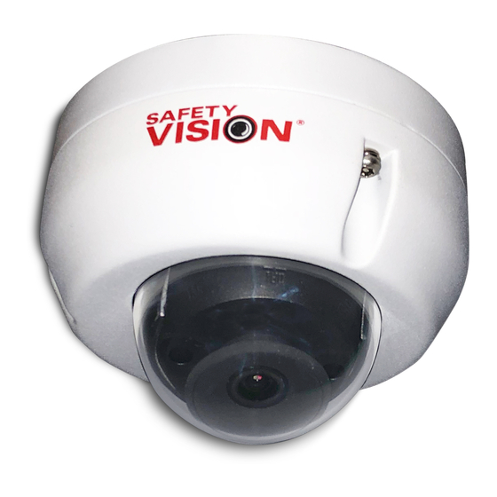
Overview 35 Series IP Camera Components 1. Cover 5. Memory Card Slot 2. Shock pad 6. Camera module 3. Infrared (IR) LED 7 . Microphone 4. Lens 8. Reset button... -
Page 7: Cables Description
Cables Description The following describes the different connectors that may be encountered on this camera series. 1. RJ45 Network Cable 2. M12 D-Coded Connectors 3. BNC Female Terminal... - Page 8 Cables Description(cont.) The relation between M12 (left) and RJ45 (right) connections are shown in the following figure and table. DESCRIPTION RJ45...
-
Page 9: Memory Card Installation
Memory Card Installation The 35 series IP cameras support a memory card for local storage. Use the following procedure to mount the memory card. 1. Unscrew the cover to disassemble the camera with supplied wrench. 2. Insert the memory card into the memory card slot. -
Page 10: Camera Mounting
Camera Mounting Before you start: Do not remove the protective film from the dome until installation is complete. Do not touch the inside of the dome. 1. Paste the drill template to the desired mounting place. - Page 11 2. Drill three guide holes and one cable hole in the ceiling into holes 1 and A on the drill template. 3. Cable wiring. Run the cable through the ceiling from hole A of the drilled template. 4. Prepare self-tapping screws. 5.
- Page 12 6. Align the mounting holes on the mounting base with the holes on the mounting surface, and insert the prepared self-tapping screws into the holes. 7 . Tighten the self-tapping screws to secure the mounting base. 8. Adjust the camera angle. 1) View the camera image via a live view on the camera’s or recorder’s firmware.
-
Page 13: Installation Of Network Cable Water-Proof Jacket (Optional)
9. Install the dome cover on the camera. 10. Remove the protective film on the dome after installation is complete. Installation of Network Cable Water-proof Jacket (Optional) If the camera is installed outdoors, you can adapt the water-proof accessory for the network cable after the camera is secured on the installation surface. -
Page 14: Water-Proof Jacket Components
Water-proof Jacket Components 1. Camera’s Network Interface 5. Waterproof Rubber Gasket Socket 6. Lock Nut 2. O-Type Gasket 7 . Network Cable from Router/ 3. Network Plug Switch 4. Waterproof Endcap Feed the plugless network cable (7) through the lock nut (6), waterproof rubber gasket (5) (the rubber gasket inset ridge must face the waterproof endcap), and the waterproof endcap (4) in order. -
Page 15: Preparation Before Using The Webcam
Preparation before using the webcam Ensure the power cable,audio cable,camera RJ-45 network connector is being connected before using the webcam. Please inquire your network administrator to set IP Address, for each webcam IP Address default as 10.100.100.101. Users are access to the default IP Address, it will take modifying or confirming the camera’s network connection settings. - Page 16 3. Web browser settings and required software components Confirmed your web browser is access to run signed ActiveX controls on PC, “download the signed ActiveX controls” setting as “prompt” , and enable “run ActiveX controls and plug-in” . All the settings route is Internet Explorer, tools, international internet options, security, reset custom level.
-
Page 17: Specifications
Specifications SPECIFICATIONS Image Sensor 1/2.8"_2.9 m CMOS Resolution 2M (1920X1080) Focal Length 2.8mm;3.6mm;6mm (optional) FOV (H / V / D) 85.8°/46.2°/98°(2.8mm) Minimum illumination Color:0.02 Lux at F2.0; B/W:0.003 Lux at F2.0; 0 Lux with IR LED ON IP Rating IP66 Power Requirement PoE (802.3 af) Operating Temperature... -
Page 18: Fcc Compliance Statement
FCC Compliance Statement NOTE This device has been tested and found to comply with the limits for a Class A digital device, pursuant to part 15 of the FCC Rules. These limits are designed to provide reasonable protection against harmful interference when the equip- ment is operated in a commercial environment. - Page 19 Memo...
- Page 20 Memo...
- Page 21 CORPORATE HEADQUARTERS 6100 W. Sam Houston Pkwy. N. Houston, TX 77041-5113 Toll Free: 800.880.8855 Main: 713.896.6600 Fax: 713.896.6640 www.safetyvision.com Mobile video solutions for enhanced safety Copyright © 2017 Safety Vision, LLC. All Rights Reserved.
Need help?
Do you have a question about the 35 Series and is the answer not in the manual?
Questions and answers