Table of Contents
Advertisement
Advertisement
Table of Contents

Related Manuals for Medline Hemo-Force MDS600INT


Summary of Contents for Medline Hemo-Force MDS600INT
-
Page 2: Table Of Contents
Table of Contents Introduction ................3 Intended Use ................3 Warnings and Cautions ............4 General Safety ................5 Control Panel Features ............. 5 Operating Instructions ............5 Alarms and Indicators .............. 8 Cleaning .................. 10 Electromagnetic Compatibility ..........11 Technical Specifications ............ -
Page 3: Introduction
Introduction The Hemo-Force is an Intermittent Pneumatic Compression System that coun- teracts blood stasis and coagulation changes; two of the three major factors that promote deep vein thrombosis (DVT) a potentially life threatening condition which can lead to pulmonary embolism. The Hemo-Force is a non-invasive mechanical prophylactic system that massages the feet or legs in a wavelike, milking motion that promotes blood flow and deters thrombosis, helping to empty pooled or static blood from the valve cusps of the... -
Page 4: Warnings And Cautions
Contraindications The use of the Hemo-Force IPCS is NOT RECOMMENDED in the following conditions: 1. Severe congestive cardiac failure 2. Severe arteriosclerosis or other ischemic vascular disease 3. Extreme deformity of the limbs 4. Known or suspected deep vein thrombosis 5. -
Page 5: General Safety
General Safety These usage and safety guidelines are IMPORTANT! Please follow them carefully. 1. It is recommended that the following guidelines be used whenever the system is being stored or transported to another location: - Temperature limitations: 40°F ~ 140°F (5°C ~ 60°C) - Relative humidity: 30% ~ 75% 2. - Page 6 4. Application of the calf and thigh sleeve(s). a. Sleeves come in identical pairs and may be used on either leg. b. When using dual sleeves the identical sleeve type (same model) must be used on both legs. Sleeve combinations are calf and calf, thigh and thigh or foot and foot.
- Page 7 end (small white connector) on the sleeve. Make certain that a click sound is heard to ensure a proper connection. See the image below: 7. Attach the other end(s) of the air hose(s) (male end) to the large white female connector(s) on the pump.
-
Page 8: Alarms And Indicators
12. To activate the timer, turn the pump on and timing will commence. The timer reflects each hour of compression. When compression is interrupted i.e. the patient is removed from therapy, the timer will suspend timing until the patient is reconnected to therapy and therapy is continued. 13. - Page 9 Alarm Fault Type Description Troubleshooting Codes Low Pressure • Leg is less than 40mmHg • Check sleeve application pressure; foot pressure is to ensure proper fit. less than 120mmHg after • Check for leaks in the sleeves 2 consecutive cycles. or air hose set and replace if •...
-
Page 10: Cleaning
Cleaning The pump: The casing of the pump is manufactured from ABS plastic which is a combination of different resins that is hard and durable through a broad range of temperatures. If soiled, it can be wiped down with a sodium hypochlorite solution to dilution of 1000ppm or with any EPA approved, hospital grade cleaner. -
Page 11: Electromagnetic Compatibility
Electromagnetic Compatibility Electric devices may interact due to electro-magnetic radiation. We recommend a safety distance of at least 3.3 feet (1 meter) especially for sensitive equipment. Upon request, we will provide you with a table for more detailed information. Recommended separation distances between portable and mobile RF communications equipment and the Hemo-Force IPCS The Hemo-Force IPCS is intended for use in an electromagnetic environment in which radiated RF disturbances are controlled. - Page 12 Article II. Guidance and manufacturer’s declaration – electromagnetic immunity The Hemo-Force IPCS is intended for use in the electromagnetic environment specified below. The customer or the user of the Hemo-Force IPCS should ensure that it is used in such an environment. Immunity test IEC 60601 test level Compliance level...
- Page 13 Article III. Guidance and manufacturer’s declaration – electromagnetic immunity The Hemo-Force IPCS is intended for use in the electromagnetic environment specified below. The customer or the user of the Hemo-Force IPCS should assure that it is used in such an environment. Immunity test IEC 60601 Compliance...
-
Page 14: Technical Specifications
Technical Specifications- The Pump Model No. MDS600INT Compression Type Intermittent Size 12.6” x 4.3” x 7.7” Weight 2.2 Kg (without Power Cord) Pressure Range Calf/Thigh Sleeve: 40mmHg +10/-5mmHg. Foot Sleeve: 120mmHg +10/-5mmHg. Input Rating AC 100-240V 50/60Hz Fuse Rating 1A 250V Classification Class I Type BF... - Page 15 Symbols Used Type BF Applied Part Manufacture Date of Manufacture Batch Code Ex. YYMMDD01XX Serial Number Caution...
-
Page 16: Servicing And Maintenance
Servicing and Maintenance In the event of a problem occurring, contact your Medline Sales representative for servicing or replacements. Servicing Protocol A) Initial Assessment (Qualitative Check) Item Qualitative Tasks Pass Fail Service Plastic Housing / Chassis Mount / Fasteners Hooks... - Page 17 B) Initial Assessment (Quantitative Check) Item Qualitative Pass Fail Service Tasks Ground Resistance less than < 0.2 ohm Max Leakage Current less than < 0.5 mA Pressure Test Minimum Pressure (LEG) 40 +10/ -5 mmHg Maximum Pressure (FT) 120 +10/ -5 mmHg Flow-rate (FT) L/min Battery Pack...
- Page 18 WARNING The control unit must be disconnected from the power supply before any maintenance or servicing work is carried out D) Open Control Unit and check that: Wiring and terminations are secure Tubing is completely intact and secure Components’ fastenings are secure General condition inside is clean If any items appear to be damaged and/or defective condition, replace with appro- priate spare part and record action.
-
Page 19: General Disassembly And Parts
General Disassembly and Parts Cleaning and replacing air filter 1. Identify the air filter module on the back the device. 2. Press the side lock to release the cap. 3. Clean the cap with a soft brush. 4. - Page 20 Battery pack replacement 1. Identify the battery back on the back of the device. 2. Unscrew the screw to release the cable cover. 3. Press the side lock to release the battery pack. 4. Remove the battery pack and check the socket for dirt and/or debris. ...
- Page 21 Opening the case/interal inspection 1. Place the device on a soft surface with the front case facing down. 2. Perform “Battery Pack Placement” procedure 1-4 to remove the battery pack. 3. Unscrew the 6 pan head screws. 4. Open the case and keep the screws in a safe place. 5.
- Page 22 3. Pull out the air tubes between compressor and valve. 4. Unscrew and remove the 2 screws securing the compressor. 5. Remove the whole compressor set out of the case. 6. Re-assemble new components in reverse order. Solenoid valve set replacement 1.
- Page 23 2. Unplug the valve power cable from PCB board. 3. Disconnect the air tube from the valve. 4. Unscrew and remove the 2 screws. 5. Remove the whole valve set. 6. Re-assemble new components in reverse order.
-
Page 24: Schematics
Fuse replacement 1. Identify the fuse module. 2. Remove the fuse(s). 3. Insert the new fuse(s). Schematics... - Page 25 Troubleshooting Guide For IPC MDSAL204230 Label, Caution MDSAL204220 Label, Instructions for IPC MDSAL204221 Manufacturer label for IPC MDSAL204119 Label, No Battery Inserted MDSAF103002 Zip Ties MDSBA106011 Air Filter MDSAL300160 Manual, Intermittent Please reference the Medline item number when ordering parts.
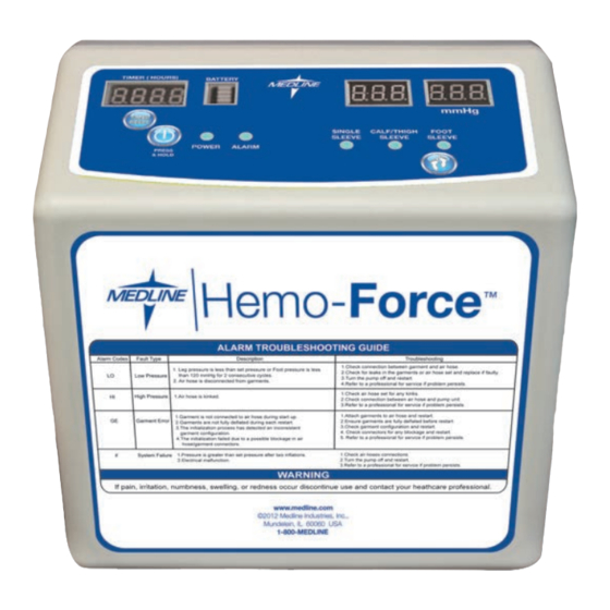
- Page 26 Sleeve Indicator/ Alarm Code Battery Indicator Pressure Time in Hours Display Window Time Reset Button Foot Mode Power Button Button to set foot sleeve Single Sleeve Mode pressure at 120 mmHg (Exclusive to Power Light Calf/Thigh Modede Hemo-Force IPCS) Alarm Light...
-
Page 27: Pressure Adjustments And Tests
Pressure Adjustments and Tests 1. Make sure the power source is 120 Volt 60 Hz. Use a power regulator to stabilize the power voltage in order to increase accuracy of pressure setting. 2. Attach the test kit to pump and manometer. 3. -
Page 28: Troubleshooting
Medline Industries, Inc. One Medline Place Mundelein, IL 60060 Medline United States 1-800-MEDLINE (633-5463) www.medline.com | info@medline.com Hemo-Force is a trademark of Medline Industries, Inc. Velcro is a registered trademark of Velcro.
Need help?
Do you have a question about the Hemo-Force MDS600INT and is the answer not in the manual?
Questions and answers