
Related Manuals for MIKOTERM MK-2.1


Summary of Contents for MIKOTERM MK-2.1
- Page 1 User manual_EN MK – 2.1 Multi 21,6/36kW Mobile electrical boiler for heating system FU-Mikoterm-MK-2.1_05/2019...
-
Page 2: Table Of Contents
CONTENT Content 1. Explanation of symbols and instructions for safe work 1.1 Explanation of symbols 1.2 Instructions for safe work Warranty and liability 1.4 Intended use 2. Device data 2.1 Overview of types 2.2 Declaration of Conformity 2.3 Instructions for operation Antifreeze agents and inhibitors Minimum spacing and flammability of construction materials 2.6 Tools, materials and auxiliary means... -
Page 3: Explanation Of Symbols And Instructions For Safe Work
Explanation of symbols and instructions for safe work 1. Explanation of symbols and instructions for safe work Important information These user manual are part of the documentation and an inherent part of the described mobile electrical heating unit. They must always be stored at the location where the mobile electrical heating unit is being used. These instructions contain important information on safe and professional installation, putting into operation and maintenance of the boiler. - Page 4 Explanation of symbols and instructions for safe work - Provide a professional examination of the electrical installation before installing the device. - All electrical operations must be carried out by a person authorized to carry out electrical operations, according to the relevant regulations.
-
Page 5: Warranty And Liability
Explanation of symbols and instructions for safe wor Warranty and liability Warranty and liability claims for personal and material damage are void if they are due to one or several of the following causes: - Unintended use of the device - Improper installation, commissioning, operation and maintenance of the device Operation of the device with defective safety devices or if the safety and protective devices are attached incorrectly or not functioning properly... -
Page 6: Device Data
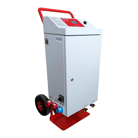
Device data 2. Device data 2.1 Overview of types Model MK-2.1 21kW Multi mobile electrical heating unit MK-2.1 36kW Multi mobile electrical heating unit 2.2 Declaration of conformity We declare that the devices have been tested in accordance with Directives 2006/95/EC (Low Voltage Directive, LVD) and 2004/108/EC (Electromagnetic Compatibility Directive, EMC). - Page 7 Device data Product description ˝ MK-2.1_21kW Multi ˝ 1 - Handcart 2 - Chassis of the device 3 - Door of the device 4 - The cover of the device 5 - Electrical plugs 6 - Main switch (0 - 1 - 2 - 3) 7 - Inlet hydraulic connection ''Geka'' 1'' 8 - Valve for inlet connection 9 - Valve for filling/drying tap on inlet connection...
-
Page 8: Product Description Mk-2.1_36Kw_˝Multi˝ Typ
Device data Product description ˝ MK-2.1_36kW Multi ˝ 1 - Handcart 2 - Chassis of the device 3 - Door of the device 4 - The cover of the device 5 – Electrical plugs 6 - Main switch (0 - 1 - 2 - 3) 7 - Inlet hydraulic connection ''Geka'' 1'' 8 - Valve for inlet connection 9 - Thermomanometer on inlet connection... - Page 9 Device data 2.9 Boiler technical data 21kW Multi Nominal power: 21,6kW ( 9×2,4kW) Power supply: 3N~230/400V 50Hz; 1N~230V 50Hz Nominal current: 3×31,3A Temperature setting range: 10 ÷ 90 °C Pressure range: 0,4bar ÷ 2,6bar Safety valve: 3bar Circulation pump: High efficiency pump Wilo-Para MSL/3-46/SC (EEI≤0,2) Expansion vessel: 8l Protection class: IP44 1 - Vessel of boiler with heaters...
- Page 10 Device data 2.10 Boiler technical data 36kW Multi -Nominal power: 36kW ( 4×9kW) -Power supply: 3N~230/400V 50Hz -Nominal current: 3×52,2A -Temperature setting range: 10 ÷ 90 °C -Pressure range: 0,4bar ÷ 2,6bar - Safety valve: 3bar -Circulation pump: High efficiency pump Wilo-Para MSL/3-46/SC (EEI≤0,2) -Expansion vessel: 10l -Protection class: IP44...
-
Page 11: Transport
Storage and transport Storage and transport 3.1 Storage Store the mobile electrical heating unit MK-2.1 in a waterproof, frost-free room in the original packaging. Conditions of mobile electric heating unit before storage: The mobile electrical heating unit is fully drained... -
Page 12: Installation And Connection To Hydraulic System
Instalation and hydraulic connection Installation and connection to hydraulic system The mobile electical heating unit must be instaled by a suitably qualified expert according to the applicable standards and regulations Manufacturer cannot be held responsible for damage due to installations errors from instalater 4.1 Description of instalation - The mobile electrical heating unit may only be installed in a space that is suitable in terms of position, size, construction properties and type of use and where risks cannot arise. - Page 13 Instalation and hydraulic connection DANGER: Injuries and/or material damages can occur by exceeding the pressure during the filling with water ! - High pressure can damage the control and safety devices as well as the vessel of device itself. - Fill the boiler with pressure that corresponds to the pressure of the opening of the safety valve. - Ensure that all control and safety parts for pressure control work properly.
- Page 14 The mobile electrical heating unit must not Danger ! be connected to more than one connection at the same time. Electricall installation of the MK-2.1 Multi 21kW MK-2.1 21 Multi Position of the main switch Connection Max. power 1N~230V 16A 2.4 kW...
-
Page 15: Description Of The Cpu Funstion And Heating
Description of the CPU 6. Description of the CPU funstion and heating 6.1 Description of the symbols on display On the front side of the boiler there is a microprocessor unit that controls the device: Appearance of a microprocessor control unit (image 1): "PROG: X"... -
Page 16: Adjust The Set Temperature And Set Power
Description of the CPU 6.1.1 Adjust the SET TEMPERATURE and SET POWER Temperature is available to adjusted in regular heating mode, when screed drying programs are not active. By briefly press ˝SET˝ button you can enter to adjustments. By buttons ˝+˝ and ˝-˝ choose parameter values. -
Page 17: Setup Menu
Description of the CPU 6.2 SETUP MENU When the boiler is turned on, the basic view appears on the display (Imag 3). In this example, that the screed drying programs are not enabled. To enter the SETUP MENU where it is possible to see essential information about the condition of the device, or to change some parameters, press the "SET"... -
Page 18: Sub-Menu ˝Time And Date
Description of the CPU DEFAULT - If this level of modulation is selected (factory setting), the boiler work with a set power until the current temperature reaches value 5 ° C below the set temperature, when it will reduce the engaged power by ~ 10% in relation to the target. When the current temperature approaches 2 °... -
Page 19: Sub-Menu ˝Energy Counter
Description of the CPU 6.2.3 SUB-MENU ˝ENERGY COUNTER˝ In this sub-menu, user can check consumption of energy. CURRENT – counter of electric energy, from boiler restart until moment of check. SCREED – consumption of energy during the screed drying process. TOTAL – energy consumption from life time of boiler. Choose one of them options by button ˝-˝... -
Page 20: Sub-Menu ˝Change Pin
Description of the CPU 6.2.5 SUB-MENU ˝ CHANGE PIN˝ By selecting this sub-menu (pressing ''OK'' while the "CHANGE PIN" flashing), the following view appears in the display (image 14). Now you need to enter a new pin-code, digit by digit, as already described earlier. Confirmation of the new PIN code is done using the ''OK'', key, after adjusted last digit, which the display shows that a new PIN code has been accepted (image 15). -
Page 21: Screed Drying Programs
Screed drying programs 7. Screed drying programs 7.1 Enter to screed drying program After you turn on the boiler, on the display is initial view with all the information (image 29) : image 29 image 30 Press the ''SET'' button to enterd in settings. SET TEMP. will start to blinking. Press ˝OK˝ to SET POWER start to blinking, and again press ˝OK˝... - Page 22 Screed drying programs – The time after which the program is canceled, if the error duration is the longer than set value. 7.2.1.1 MAX DECAY TIME MAX DECAY TIME is expressed in format hh : mm. To enter the submenu press ''OK'' until the flashing '' MAX DECAY TIME ''. The factory default setting is 1h : 0min (image 34), the setting range is from 5min to 10h in steps of 5min.
- Page 23 Screed drying programs – The maximum allowed difference between the boiler temperature set value and 7.2.1.3 ALOWED TEMPERATURE DEVIATION actual boiler temperature. Comparison begins after 6 hours from the start of the program. The value of this parameter is expressed in ºC.
-
Page 24: Program Settings
Screed drying programs 7.3 PROGRAM SETTINGS – If in Basic menu (image 31), using the ''-'' and ''+'' select this submenu, you can see the following screen (image 39): image 39 In this sub-menu (image 39) you can reviewed and adjusted screed drying programs. Program 1: ''FUNCTION HEATING'' (image 40) and program 2: ''FUNCT. - Page 25 Screed drying programs 7.3.2 FUNCT. & PROOF HEATING image 41 Program 2: ''FUNCT. & PROOF HEATING'' (image 41) is set at the factory and can not be changed. Duration of the program is 25 days. Factory setting: -The first 3 days keep the temperature of 25 °C, -From 4th to 7th days, included 7th day maintains 55 °C.
- Page 26 Screed drying programs 7.3.3 INDIVIDUAL HEATING Program 3: INDIVIDUAL HEATING (image 42) is not the factory setting and it is necessary to completely adjust before starting. image 42 Maximum duration of the program 3: ''INDIVIDUAL HEATING'' is 30 days. Outlet boiler temperature must be set for each day of work program in particular.
-
Page 27: Start Heating Program
Screed drying programs – In the Basic Menu (image 23), using the ''-'' and ''+'' button is selected submenu 7.4 START HEATING PROGRAM ''START HEATING PROGRAM'', display appears the following view (image 36): image 45 Use the ''-'' and ''+'' button to select the program that needs to start up. While the chosen program blinks, pressing ''OK'' starts launching procedure, and the display changes to the following (image 46), where the first option that is flashing ’’NO'' (no start program), to prevent accidental starting of the program. - Page 28 Screed drying programs Before start the program, the cpu prepares memory to make sure that all the program data (from future program) will be saved. If is 10 files saved in memory, oldest will be erased. On this way CPU make free space for new data from program which prepare to start. During the preparation, on screen appears view (image 50).
-
Page 29: Program Status
Screed drying programs 7.5 PROGRAM STATUS – This menu item appears only if an active some of the programs for screed drying.If in the Basic Menu (image 24), using the ''-'' and ''+'' button is selected this submenu, confirm by pressing the ''OK'' button, the display will show the veiw from image 53. -
Page 30: Stop Heating Program
Screed drying programs – If the submenu ''PROGRAM STATUS'' determined the current status of the program in progress graphs 7.5.2 GRAPHIC DISPLAY (GRAPHIC DISPLAY), pressing ''OK'' until the flashing ''GRAPHIC DISPLAY''opens the following screen is displayed: image 58 On this view (image 58), you can see a complete program that is executed, the number of current days is blinking, and dot below the graphics that also marks the current day that is underway to make it easier to gain insight into the part of the program is executed and a part of the program, which has yet to is executed. - Page 31 Screed drying programs 7.7 RECORDING DATA ON USB MEMORY STICK In memory of the device is stored for each activated screed drying program 2 records. First in .csv (Excel) format, the other in .svg format, both of which are located in a common file whose name is drawn from the name of the program activated (P1, P2 or P3) which added to the program start date (in the format dd- mm-yy) and the program start time (format hh: mm).
- Page 32 Screed drying programs image 66 If the file is successfully saved on USB memory, a notification will be displayed on the display, as well as the question to download the another file (image 66). If the selected option ''NO'', which flashes, on the display appears notification that it completed the transfer of data and should disconnect the USB memory (image 67).
-
Page 33: Review And Printing Data From Completed Screed Drying Program
Screed drying programs 7.8 REVIEW AND PRINTING DATA FROM COMPLETED SCREED DRYING PROGRAM When the data of the executed program from a device dowloaded on a USB memory stick, new folder is created. Folder name is created from: Serial number of CPU (999999), date of folder creation - downoading from boiler (23.08.2019.) and time of folder creation (10h 59'). When USB memory stick is connected on computer and open, downloaded folder with described name is avaliable. - Page 34 Screed drying programs SVG file is more transparent, on one page is graphically displayed the temperature of the system in relation to the set temperature value from the program, in the entire duration of the program. Example of .svg file (image 73): Image 73 This file can not be changed, and additional information must be entered manually after printing.
-
Page 35: Menu Maps
Screed drying programs 7.9 MENU MAPS hold SET 5sec MAIN MENU (program is not active) (program is active) INSERT PIN Set SETPOINT Temperature by ↓/↑ 1111/_ _ _ _ Set POWER by ↓/↑ (prog is active) (prog is not active) PROG OFF PROG: X ↓/↑... - Page 36 Screed drying programs BASIC MENU of screed drying program HEATING PROGRAM IS NOT ACTIVE HEATING PROGRAM IS ACTIVE ↓/↑ ↓/↑ ↓/↑ SYSTEM PROGRAM PROGRAM STOP HEATING START HEATING SETINGS SETINGS PROGRAM STATUS PROGRAM FUNCTION FUNCTION MAX DECAY ABORT: NO DATA HEATING HEATING TIME...
-
Page 37: Codes
Codes 8. CODES WARNING codes A1 - Warning: approaching the lower limit of the allowed pressure (0.8 bar) SHOULD BE DONE - Fill the system with water to the necessary pressure A2 - Warning: approaching the upper limit of the allowed pressure (2.2 bar) SHOULD BE DONE - Bring the system to the required pressure A3 - Warning: approaching the lower limit of the allowed temperature where there is risk of freezing (3˚C degrees) of the HEATING SYSTEM... -
Page 38: Faults And Their Remedy
Faults and their remedy FAULTS AND THEIR REMEDY Remedy of faults on the regulation and hydraulics must be carried out by an authorized company. Use only original parts for repairs. fault: description: cause: measure: - boiler is disconnected from - Ensure power supply electricity voltage The display does not... -
Page 39: Pump Wilo-Para Msl/6-43/Sc
Pump Wilo-Para MSL/6-43/SC 10 Pump Wilo-Para MSL/6-43/SC 1. Composite OEM pump housing 2. Pump inlet MS ¾ 'SN 3. Pump output terminal composite ¾ '' SN 4. Automatic air vent 5. Safety valve 3bar 6. Pressure sensor 7. Pump head with electronics 8. - Page 40 Mikoterm d.o.o. does not assume responsibility for possible errors in this booklet produced by printing or duplication, all images and schemes are in principle, it is necessary to adapt each to the actual situation on the ground. In any case, Mikoterm reserves the right to make changes that it deems necessary on its products.
Need help?
Do you have a question about the MK-2.1 and is the answer not in the manual?
Questions and answers