Table of Contents
Advertisement
Advertisement
Table of Contents

Related Manuals for Ametek 5000 Series

Summary of Contents for Ametek 5000 Series
- Page 1 Automotive Immunity QUICK-START GUIDE Test Generators AND SAFETY INSTRUCTIONS 5000-series NSG 5500x PA 5840x PA 5740x NSG 5071x Version: 1.00 08.04.2021 Replaces: Filename: Quick Start and Safety 5000-series V1.00 EN Print date: 4.29.2021 Quick Start and Safety Guide V 1.00 1 / 27...
- Page 2 4153 Reinach BL1 Switzerland Phone: +41 61 204 41 11 Fax: +41 61 204 41 00 URL : www.ametek-cts.com Copyright © 2021 AMETEK CTS GmbH All right reserved. Information in earlier versions. Specifications subject to change. V 1.00 2 / 27...
-
Page 3: Table Of Contents
AMETEK CTS Automotive Immunity Test Generators Contents Safety..........................4 1.1. Safety Aspects ............................ 4 1.2. Safety and warning label on the device ....................4 1.3. Responsibility of the operator ......................5 1.4. General hazard ........................... 5 1.5. Qualification of personnel ........................6 1.6. -
Page 4: Safety
AMETEK CTS Automotive Immunity Test Generators Safety 1.1. Safety Aspects Observe all precautions to assure your personal safety. The generators comply with Installation Category II (excess voltage section). Pay special attention to safety and operation details! 1.2. Safety and warning label on the device Take note of the following explanations of the symbols used in order to achieve the optimum benefit from this manual and to ensure safety during operation of the equipment. -
Page 5: Responsibility Of The Operator
Neither AMETEK CTS GmbH, nor any of the subsidiary sales organizations can accept any responsibility for personnel, material or inconsequential injury, loss or damage that results from improper use of the equipment and accessories. -
Page 6: Qualification Of Personnel
AMETEK CTS Automotive Immunity Test Generators Only approved accessories, connectors, adapters, etc. are to be used to ensure safe operation. 1.5. Qualification of personnel The generator must be operated only by authorized and trained specialists with detailed knowledge of the international, national or manufacturer’s test standard. -
Page 7: 3-Phase Eut Power Lines
AMETEK CTS Automotive Immunity Test Generators First check the 115 V / 230 V voltage selector where applicable! Do not connect 230 VAC into the 115 VAC units. The result could be a severely damaged unit. Figure 5 - Voltage Selection If power to the equipment of Class I is supplied by an auto-transformer which is connected to a higher supply voltage, the base of the auto-transformer must be connected to the neutral of the power supply. -
Page 8: Safety Functions
AMETEK CTS Automotive Immunity Test Generators Safety functions The test area must be organized so that only those involved in the test may enter it. In the case that the safety circuit is used to control the complete area, an additional interlock contact must be used to directly protect the operator from contact with the DUT. -
Page 9: Testing And Precautions
AMETEK CTS Automotive Immunity Test Generators Testing and Precautions All tests produced EMC generators are immunity tests on electronic equipment or devices. These tests are potentially dangerous to the operator. It is the responsibility of the user to avoid critical failures and risks to the environment and the operator. -
Page 10: Interference To The Environment
Automotive Immunity Test Generators 3.5. Interference to the environment CAUTION: The AMETEK CTS interferences generators are instruments with a functionally emission of electromagnetic interference during the test (e.g., ESD, EFT, conducted RF, etc.). Therefore, a disturbance of the environment cannot be excluded. - Page 11 AMETEK CTS Automotive Immunity Test Generators Cables and connectors can be overloaded by high voltages or energies. Due to internal damage of components fire and/or explosion may occur. Unintended use of the EUT may cause hazardous situations in the vicinity of the test area.
-
Page 12: Operating Elements, Indications, Connections 5000-Series
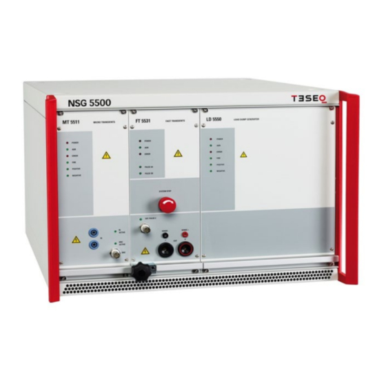
AMETEK CTS Automotive Immunity Test Generators Operating elements, indications, connections 5000-series 4.1. NSG 5500 front view NSG 5500 chassis BNC output connector MT 5511 module RI LED Status LED display FT 5531 module RI connector System Stop BNC status LED... - Page 13 AMETEK CTS Automotive Immunity Test Generators Status LED display LD 5550 POWER: Indicates power ”ON” ADR: Flashes when unit addressed ERROR: Indicates an error condition FIRE: Blinks when the pulse is fired POSITIV: Lights when pulse 5 is selected NEGATIV:...
-
Page 14: Nsg 5500 Rear View
AMETEK CTS Automotive Immunity Test Generators 4.2. NSG 5500 rear view NSG 5500 chassis Ventilation CDN 5501 Ventilation for HV PSU 5500 module Ethernet interface HV PSU 5500 module USB interface Bus expansion GPIB interface 9 pin DSub remote connector... - Page 15 AMETEK CTS Automotive Immunity Test Generators Remote 9 pin DSub port. Pin2: Reference signal for pin3 (GND) Pin3: Trigger Out when a pulse is fired Pin7: Stops the pulse. Battery voltage is not switched off! Main source IN Input for dc voltage main source, e.g. PA5840 for battery voltage levels to operate the EUT.
- Page 16 AMETEK CTS Automotive Immunity Test Generators 18 Circuit breaker Safetly feature. Interrupts the line inside CND5501 if the current output exceeds 100A. V 1.00 16 / 27...
-
Page 17: Pa 5840 Front View
AMETEK CTS Automotive Immunity Test Generators 4.3. PA 5840 front view Voltage display POWER switch SYSTEM STOP switch GAIN Current display Cooling CURRENT LIMIT Sense lines ERRORS indicators + / - output COMPENSATION MODES BNC I INPUT CURRENT LIMITATION CONTROL... - Page 18 AMETEK CTS Automotive Immunity Test Generators Made selection is indicated by LED. CURRENT LIMITATION Select the required current limitation, selection indicated by LED. PEAK OFF / 3* I CONTROL / 3* I MAX. Selection allows inrush current flow. OUTPUT RANGE Select between 2 different output voltage ranges, 30V / 60V, selection indicated by LED.
-
Page 19: Pa 5840 Rear View
AMETEK CTS Automotive Immunity Test Generators 4.4. PA 5840 rear view Cooling for control unit Fans and protection covers for cooling. Ensure a proper air flow, keep at least 0.5m to any blocking items such as walls. Control cable CU/PS Internal control cable control unit / power stage (pre-wired). -
Page 20: Pa 5740 Front View
AMETEK CTS Automotive Immunity Test Generators 4.5. PA 5740 front view Cooling Power switch COMPENSATION modes Sense lines ERRORS indicators +/- OUTPUT Voltage display CONTROL Current display GAIN Cooling Fans and protection covers for cooling. Ensure a proper air flow, keep at least 0.5m to any blocking items... -
Page 21: Pa 5740 Rear View
AMETEK CTS Automotive Immunity Test Generators CONTROL 9 pins DSub connection to control voltage and current output of the amplifier, connected to the NSG 5500. 1: Current limiter, 0-10VDC 2: Reference signal of Pin1 (GND) 3: Voltage control, -10 up to +10VDC 4: Reference signal of Pin3 (GND) Supported bandwith: DC –... -
Page 22: Nsg 5071 Top / Front View
AMETEK CTS Automotive Immunity Test Generators 4.7. NSG 5071 top view / front view BNC ARB input Pulse C output Pulse selection and table +/- battery input Counter 1 Power switch Signal source 1 BNC D Signal source 2 BNC C... - Page 23 AMETEK CTS Automotive Immunity Test Generators Pulse C output DUT output for pulses C +/- battery input Either connect a regular car battery 12V or connect a battery simulator, input voltage up to 15V 10 Power switch To power up and operate the unit. An original car battery (12V) or battery simulator must be connected.
-
Page 24: Operation
AMETEK CTS Automotive Immunity Test Generators Operation 5.1. Test Setup See below a test setup sample using 2 PA units connected to the NSG 5500. 5.2. Get started Establish all required cablings between NSG 5500 and PA 5840 (see sample setup above) •... -
Page 25: Software Operation
AMETEK CTS Automotive Immunity Test Generators 5.3. Software Operation Once the software is installed and connected to the system, configured the remote interface, define and set the voltage source and the corresponding arb-channel, select a pulse and its parameters and start the test. -
Page 26: Tests With Clamps And Other Couplers
WARNING: Coupling clamps are dangerous to touch and must not be approached during the test run! WARNING 5.4.1. Verification Accessories Consult the datasheet for verification accessories. Only genuine AMETEK CTS and EM Test accessories are supported. Consult the standard for proper usage and when verification must take place. V 1.00 26 / 27... -
Page 27: Maintenance, Adjustments, Replacement Of Parts
EM TEST and Teseq devices can be returned to AMETEK CTS in Switzerland or to their agency for adequate disposal. Alternatively, the equipment can be handed over to a specialized enterprise for disposal of electronic devices.
Need help?
Do you have a question about the 5000 Series and is the answer not in the manual?
Questions and answers