Olympus ESG-400 Instructions Manual
Electrosurgical generator
Hide thumbs
Also See for ESG-400:
- Maintenance manual (110 pages) ,
- Instructions for use manual (160 pages) ,
- System reference manual (58 pages)

Related Manuals for Olympus ESG-400


Summary of Contents for Olympus ESG-400
- Page 1 INSTRUCTIONS ELECTROSURGICAL GENERATOR ESG-400 USA: CAUTION: Federal Law restricts this device to use by, or on the order of, a physician.
-
Page 3: Table Of Contents
Connection to an AC mains power supply ................Automatic mist & smoke evacuation system/function (when using the compatible high flow insufflation unit) ...................... Connection of footswitch ....................... Connection of neutral electrode (for monopolar treatment only)........... Connection of HF instruments ....................W7.091.601 ELECTROSURGICAL GENERATOR ESG-400... - Page 4 Software version ........................102 Safety test ..........................103 Service ........................... 105 Output volume control......................105 Brightness control ........................107 Chapter 7 Care, Storage and Disposal ..............108 Care ............................108 Storage ..........................109 Disposal ..........................110 ELECTROSURGICAL GENERATOR ESG-400 W7.091.601...
- Page 5 Alarm information..........................156 Tone information ..........................157 List of abbreviations Alternating Current Electromagnetic Compatibility Electrosurgical Generator Fast Spark Monitor High Frequency HPCS High Power Cut Support Implanted Cardioverter Defibrillator Implanted Electronic Device RCAP Resistance Controlled Automatic Power W7.091.601 ELECTROSURGICAL GENERATOR ESG-400...
-
Page 6: Labels And Symbols
Important Information – Please Read Before Use Labels and Symbols Safety-related labels and symbols are attached on the locations shown below. If labels or symbols are missing or illegible, contact Olympus. Function-related symbols are described in chapter 2.1, “Symbols and Descriptions”. Output insulated from earth... -
Page 7: Important Information - Please Read Before Use
Important Information – Please Read Before Use Important Information – Please Read Before Use Intended use The ESG-400 is an electrosurgical generator intended for tissue cutting and coagulation in open, laparoscopic and endoscopic surgery in conjunction with electrosurgical accessories and ancillary equipment. Contraindications:... -
Page 8: User Qualifications
/ or equipment damage may result. Repairs must only be carried out by Olympus or a firm authorized by Olympus. Some problems that appear to be malfunctions may be corrected by referring to chapter 8, “Troubleshooting”. -
Page 9: Signal Words
Always prepare for an emergency operation in case of unintentional patient burn, bleeding and perforation. Follow the dangers, warnings and cautions given below when handling this electrosurgical generator. This information is to be supplemented by the dangers, warnings and cautions given in each chapter. W7.091.601 ELECTROSURGICAL GENERATOR ESG-400... - Page 10 − Electrosurgical equipment whose safety in combined use is not guaranteed. The electrosurgical generator complies with the electromagnetic compatibility (EMC) standard. Nevertheless, when electrosurgical generator is active it may disturb neighboring ELECTROSURGICAL GENERATOR ESG-400 W7.091.601...
- Page 11 (refer to “Mode characteristics”, “Output characteristics” in the Appendix, and the instruction manual of the accessory). For a list of compatible neutral electrodes, refer to “Specifications” in the Appendix. For compatible W7.091.601 ELECTROSURGICAL GENERATOR ESG-400...
- Page 12 If liquid gets on or into electrosurgical generator, terminate operation immediately and contact Olympus. CAUTION Injury during servicing When the housing is opened, there is a danger of electric shock. The electrosurgical generator must only be serviced by authorized technicians.
- Page 13 This does not apply to instruments intended for use in conjunction with conductive fluids. The endoscopic treatment performed should not include an operation in which part of the treated tissue (polyp head, etc.) or part of the W7.091.601 ELECTROSURGICAL GENERATOR ESG-400...
- Page 14 B or BF applied parts. When using the electrosurgical generator on or in the vicinity of the heart, be sure to use it with minimum necessary output. Spark discharge during operation may affect the heart. ELECTROSURGICAL GENERATOR ESG-400 W7.091.601...
- Page 15 WARNING Ignitable gas in the gastro-intestinal tract If the intestines contain a flammable gas, replace this gas with air or a non-flammable gas before performing the operation, to minimize the risk of fire or explosion. W7.091.601 ELECTROSURGICAL GENERATOR ESG-400...
- Page 16 To prepare for possible accidents, emergency equipment life-saving, intubation appropriate pharmaceuticals should be located in or near the procedure room. Always prepare spare electrosurgical generator or an alternative procedure to avoid ELECTROSURGICAL GENERATOR ESG-400 W7.091.601...
- Page 17 Studies have shown that smoke generated during electrosurgical procedures irritating and potentially harmful to surgical personnel. These studies recommend the use of surgical masks and adequate ventilation of smoke by the use of surgical smoke evacuators or other means. W7.091.601 ELECTROSURGICAL GENERATOR ESG-400...
-
Page 18: Legal Information
Legal information In the US and other countries, Celon and RCAP are registered trademarks of Celon AG medical instruments and Olympus, RFCoag, ESG and AFU are trademarks or registered trademarks of Olympus Corporation, Olympus Medical Systems Corporation and / or their affiliates. -
Page 19: Chapter 1 Checking The Package Contents
If the electrosurgical generator is damaged, a component is missing or you have any questions, do not use the electrosurgical generator and contact Olympus. Footswitch with cable (WB50402W) Electrosurgical generator (ESG-400) Instruction manual W7.091.601 ELECTROSURGICAL GENERATOR ESG-400... -
Page 20: Chapter 2 Nomenclature And Functions
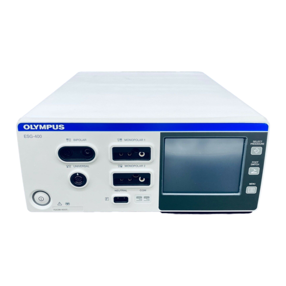
Front panel Power on / off Neutral electrode – non-split type Neutral electrode – split type Select procedure Footswitch Menu BIPOLAR socket MONOPOLAR 1 socket UNIVERSAL socket MONOPOLAR 2 socket Touch-screen Double footswitch Single footswitch Autostart Plus ELECTROSURGICAL GENERATOR ESG-400 W7.091.601... - Page 21 Chapter 2 Nomenclature and Functions Minus Return Cancel Save procedure Delete procedure Languages Touch tone on Touch tone off Software version Safety test Service Volume Brightness Select procedure (in title line) Menu (in title line) Toggle Previous Next Numeric Alphabetic W7.091.601 ELECTROSURGICAL GENERATOR ESG-400...
- Page 22 Communication indicator Reset RCAP Resistance Controlled Automatic Power Reference to BIPOLAR socket Reference to MONOPOLAR 1 socket Reference to UNIVERSAL socket Reference to MONOPOLAR 2 socket Rear panel Volume Footswitch LINK-IN LINK-IN socket LINK-OUT LINK-OUT socket ELECTROSURGICAL GENERATOR ESG-400 W7.091.601...
-
Page 23: Front Panel
This button is used to open the “Select Procedure screen” to recall saved settings. MENU push button This button is used to open the “Menu screen” to control several functions (save or delete a procedure, control the touch tone, output volume and brightness as well as other functions). W7.091.601 ELECTROSURGICAL GENERATOR ESG-400... - Page 24 This indicator illuminates green if a non-split neutral electrode is connected. Neutral electrode socket This socket connects the plug of a neutral electrode for monopolar application. UNIVERSAL socket This socket connects the plug of an Olympus HF instrument with HF instrument recognition. ELECTROSURGICAL GENERATOR ESG-400 W7.091.601...
-
Page 25: Rear Panel
This socket serves as a connection to the mains power supply via a power cord. LINK-OUT socket This socket connects the plug (14-pin) of a cable connected to peripheral equipment. LINK-IN socket This socket connects the plug (26-pin) of a cable connected to peripheral equipment. W7.091.601 ELECTROSURGICAL GENERATOR ESG-400... -
Page 26: Bottom Panel
3.7 “Connection of neutral electrode” and chapter 3.8 “Connection of HF instruments”. 2.4 Bottom panel Docking socket This socket connects the plug (7-pin) of a docking connector to connect peripheral equipment. ELECTROSURGICAL GENERATOR ESG-400 W7.091.601... -
Page 27: All Screen
If an output power level is set to zero, “--” will be displayed instead of numbers. Effect The number shows the effect as selected in the “Set screen”. For RFCoag mode the RCAP function can be selected instead of an effect (refer to chapter 5.4, “Output setting”). W7.091.601 ELECTROSURGICAL GENERATOR ESG-400... -
Page 28: Set Screen
“--” will be displayed instead of numbers. Effect The number shows the selected effect. For RFCoag mode the RCAP function can be selected instead of an effect (refer to chapter 5.4, “Output setting”) ELECTROSURGICAL GENERATOR ESG-400 W7.091.601... -
Page 29: Mode Screen
Return button Press this button to return to the “Set screen.” 2.8 Footswitch with two pedals The footswitch with two pedals (Olympus REF: WB50402W) is included in delivery. Cut pedal (yellow color) This pedal is used to activate the selected cutting mode. -
Page 30: Footswitch With One Pedal (Optional)
Chapter 2 Nomenclature and Functions 2.9 Footswitch with one pedal (optional) The footswitch with one pedal (Olympus REF: WB50403W) is an optional item which may be purchased separately. Coagulation pedal (blue color) This pedal is used to activate the selected coagulation mode. -
Page 31: Communication Cable 0.25 M (Maj-1871, Optional, This Cable Is Required For The Connection With The Compatible Ultrasonic Generator)
2.11 Communication cable 0.25 m (MAJ-1871, optional, this cable is required for the connection with the compatible ultrasonic generator) The communication cable 0.25 m (Olympus REF: MAJ-1871) is a separate accessory and connects the electrosurgical generator with the compatible ultrasonic generator. -
Page 32: Communication Cable 10 M
(UHI-2/3)) The communication cable 10 m (Olympus REF: MAJ-1872) is a separate accessory and connects the electrosurgical generator with the adapter for the compatible high flow insufflation unit. -
Page 33: Adapter For Uhi-2/3 (Maj-1873, Optional, This Adapter Is Required For The Connection With The Compatible High Flow Insufflation Unit (Uhi-2/3))
2.13 Adapter for UHI-2/3 (MAJ-1873, optional, this adapter is required for the connection with the compatible high flow insufflation unit (UHI-2/3)) The adapter for UHI-2/3 (Olympus REF: MAJ-1873) is a separate accessory and connects the electrosurgical generator with the high flow insufflation unit. Front... -
Page 34: Chapter 3 Installation And Connections
Chapter 3 Installation and Connections The electrosurgical generator must be properly installed and commissioned by Olympus or by a person or firm commissioned and authorized by the manufacturer. Prepare the electrosurgical generator and other equipment to be used with this electrosurgical generator before each use. -
Page 35: Flow Chart For Installation Work
3.4 Connection to an AC mains power supply Automatic mist & smoke evacuation page 37 system/function page 42 3.6 Connection of footswitch page 43 3.7 Connection of neutral electrode page 49 3.8 Connection of HF instruments W7.091.601 ELECTROSURGICAL GENERATOR ESG-400... -
Page 36: Installation Of Electrosurgical Generator
Before using an optional item, thoroughly review and understand the instruction manual provided with that item check compatibility with the electrosurgical generator. Specifications, design and accessories are subject to change without any notice or any obligation of the manufacturer. ELECTROSURGICAL GENERATOR ESG-400 W7.091.601... -
Page 37: Connection Of Peripheral Equipment
“All screen” or “Set screen” (see chapter 2.5, “All screen”). The threaded holes on the bottom left and right of the rear panel are left open intentionally to attach peripheral equipment with electrosurgical generator via fixture plates. W7.091.601 ELECTROSURGICAL GENERATOR ESG-400... -
Page 38: Connection To An Ac Mains Power Supply
If the voltage of the facility is different from the voltage indicated on the type plate of the electrosurgical generator, contact Olympus. ELECTROSURGICAL GENERATOR ESG-400 W7.091.601... -
Page 39: Automatic Mist & Smoke Evacuation System/Function (When Using The Compatible High Flow Insufflation Unit)
(when using the compatible high flow insufflation unit) When the electrosurgical generator is combined with an Olympus high flow insufflation unit (UHI-2/3) via a communication cable (MAJ-1871 or 1872), the smoke and mist produced in the abdominal cavity can be evacuated simultaneously with the electrosurgical output. - Page 40 When using the electrosurgical generator with the compatible ultrasonic generator and the compatible high flow insufflation unit (UHI-2 or UHI-3) simultaneously, contact Olympus. Preparation Prepare the adapter for UHI-2/3 and the communication cable The compatible high flow insufflation unit cannot be connected directly to the electrosurgical generator.
- Page 41 Chapter 3 Installation and Connections Correct connection System connector Electrosurgical generator High flow insufflation unit (UHI-2, UHI-3) Adapter for UHI-2/3 Incorrect connection System connector High flow insufflation Electrosurgical generator unit (UHI-2, UHI-3) Adapter for UHI-2/3 Figure 3.2 W7.091.601 ELECTROSURGICAL GENERATOR ESG-400...
- Page 42 LINK-OUT connector of the compatible electrosurgical generator. Connecting the communication cable 0.25 m to the compatible ultrasonic generator Connect the other plug of the communication cable 0.25 m to the LINK-IN or LINK-OUT connector of the ultrasonic generator. ELECTROSURGICAL GENERATOR ESG-400 W7.091.601...
- Page 43 System connector Adapter for UHI-2/3 Communication cable 0.25 m Communication cable (MAJ-1871) 10 m (MAJ-1872) Incorrect connection Compatible high flow Compatible ultrasonic Electrosurgical generator insufflation unit (UHI-2, UHI-3) generator System connector Adapter for UHI-2/3 Figure 3.3 W7.091.601 ELECTROSURGICAL GENERATOR ESG-400...
-
Page 44: Connection Of Footswitch
Do not connect products other than the footswitch for this electrosurgical generator to the footswitch socket. Otherwise, the footswitch might not function and may cause patient injury and / or damage of the equipment. ELECTROSURGICAL GENERATOR ESG-400 W7.091.601... -
Page 45: Connection Of Neutral Electrode (For Monopolar Treatment Only)
Reattach the neutral electrode or use a new plate. The contact quality monitor indicator for split neutral electrode will only light green while the contact between the neutral electrode and the skin of the patient is within an acceptable resistance range (see “Specifications” in the Appendix). W7.091.601 ELECTROSURGICAL GENERATOR ESG-400... - Page 46 (see “Specifications” in the Appendix). CAUTION No error message or audible signal will be generated if an unintended detachment of the non- split neutral electrode occurs. Therefore, it is not recommended to use non-split neutral electrodes. ELECTROSURGICAL GENERATOR ESG-400 W7.091.601...
- Page 47 Do not use the neutral electrode if it has been damaged, modified or has sharp edges. This may cause patient burns. This electrosurgical generator should be used combination with neutral electrodes shown in “Specifications” in the Appendix. W7.091.601 ELECTROSURGICAL GENERATOR ESG-400...
- Page 48 E202). If a neutral electrode failure is indicated and an HF instrument is already placed at the treatment site, mechanical tissue cutting by the HF instrument may occur and cause patient bleeding or perforation. ELECTROSURGICAL GENERATOR ESG-400 W7.091.601...
- Page 49 (suitable for 2 pin plugs with 2.5 mm pin diameter and pin spacing 10 mm, US standard) on the front panel of the electrosurgical generator (see figure 3.5). Figure 3.5 W7.091.601 ELECTROSURGICAL GENERATOR ESG-400...
- Page 50 3.7 will appear. Press the “OK button” to continue and the display returns to the last used screen. Verify that the contact quality monitor indicator for non-split neutral electrodes illuminates green. Confirmation window Figure 3.7 ELECTROSURGICAL GENERATOR ESG-400 W7.091.601...
-
Page 51: Connection Of Hf Instruments
HF instrument may occur and cause bleeding or perforation of the patient. CAUTION Olympus HF instruments should be used for electrosurgical procedures. For details, refer to the instruction manual of the HF instrument. If you have any questions concerning the applicability of your HF instrument, please contact Olympus. - Page 52 WARNING Do not connect a 2-pin 4 mm plug (e.g. from monopolar hand-switch activated forceps) to the MONOPOLAR 1 socket or to the MONOPOLAR 2 socket. Connecting this type of instrument may damage the generator. ELECTROSURGICAL GENERATOR ESG-400 W7.091.601...
- Page 53 8 / 4 mm pin diameter (Erbe standard). UNIVERSAL socket Suitable for 7 pin bipolar multifunctional plugs (Olympus standard) and offers HF instrument recognition. For a detailed description, refer to chapter 5.4, “Output setting”. Checking the HF instrument Confirm that the HF instrument cable and HF instrument plug are not damaged.
-
Page 54: Chapter 4 Inspection
“Troubleshooting”. irregularity still suspected after consulting chapter 8, contact Olympus. Damage or irregularity may compromise patient or user safety and may result in more severe equipment damage. ELECTROSURGICAL GENERATOR ESG-400 W7.091.601... -
Page 55: Flow Chart For Inspection Work
Inspection of connection between peripheral page 56 equipment and the electrosurgical generator Inspection of touch-screen and push button page 57 page 60 Inspection of footswitch connection page 61 Inspection of alarm system page 61 4.7 Procedure after inspection W7.091.601 ELECTROSURGICAL GENERATOR ESG-400... -
Page 56: Inspection Of Power
Inspection of the power switch, touch-screen and push buttons Switch on the electrosurgical generator with the power switch. The power switch illuminates. The touch-screen lights up. The push buttons illuminates. The contact quality monitor indicator for split neutral electrodes illuminates. ELECTROSURGICAL GENERATOR ESG-400 W7.091.601... - Page 57 4.2) is displayed and the electrosurgical generator is ready for use. Confirm that a tone can be heard at the same time as the “Start screen” is displayed. Start screen Figure 4.1 All screen Figure 4.2 W7.091.601 ELECTROSURGICAL GENERATOR ESG-400...
-
Page 58: Inspection Of Connection Between Peripheral Equipment And The Electrosurgical Generator
Confirm that the peripheral equipment and the electrosurgical generator are connected properly. Confirm that the generators are switched on. If the communication indicator does not illuminate even after the above check, contact Olympus. ELECTROSURGICAL GENERATOR ESG-400 W7.091.601... -
Page 59: Inspection Of Touch-Screen And Push Buttons
After pressing the “Plus button” / “Minus button”, confirm that the output level is changed accordingly. Otherwise, inappropriate output can cause burns to the patient and / or user, patient bleeding and / or perforation. W7.091.601 ELECTROSURGICAL GENERATOR ESG-400... - Page 60 / “Minus button”. Press the “Toggle button”. Pressing the “Toggle button” changes the effect. Press the “Return button”. The screen changes from the “Set screen” to the “All screen” (see figure 4.4). All screen Set screen Figure 4.4 ELECTROSURGICAL GENERATOR ESG-400 W7.091.601...
- Page 61 The “Menu screen” appears showing different control buttons. MENU Figure 4.5 Press the “Return button”. The screen changes from the “Menu screen” to the “All screen” as shown in figure 4.6. All screen Menu screen Figure 4.6 W7.091.601 ELECTROSURGICAL GENERATOR ESG-400...
-
Page 62: Inspection Of Footswitch Connection
“MONOPOLAR 1 output socket.” Disconnect the footswitch plug from the electrosurgical generator. The “Double footswitch button” is black again. Double footswitch button Single footswitch button Footswitch screen Figure 4.8 ELECTROSURGICAL GENERATOR ESG-400 W7.091.601... -
Page 63: Inspection Of Alarm System
Switch off the electrosurgical generator with the power switch. The illumination of the power switch is off. The touch-screen is off. The illumination of the push buttons is off. The contact quality monitor indicator for split neutral electrodes is off. W7.091.601 ELECTROSURGICAL GENERATOR ESG-400... -
Page 64: Chapter 5 Operation
“Troubleshooting”. irregularity still suspected after consulting chapter 8, contact Olympus. Damage or irregularity may compromise patient or user safety and may result in more severe equipment damage. ELECTROSURGICAL GENERATOR ESG-400 W7.091.601... -
Page 65: Flow Chart For Operation Work
64 5.2 Turn on the electrosurgical generator Automatic mist & smoke evacuation page 65 system/function page 67 5.4 Output setting page 79 5.5 Output of energy page 84 5.6 Procedure after use W7.091.601 ELECTROSURGICAL GENERATOR ESG-400... -
Page 66: Turn On The Electrosurgical Generator
Connections”. For the connection check method refer to chapter 4, “Inspection”. Turn the power on. Press the power switch of the electrosurgical generator. For the “power on” check method, refer to chapter 4.2, “Inspection of power”. ELECTROSURGICAL GENERATOR ESG-400 W7.091.601... -
Page 67: Automatic Mist & Smoke Evacuation System/Function (When Using The Compatible High Flow Insufflation Unit)
For the connection method, see chapter 3.5, “Automatic mist & smoke evacuation system/function (when using the compatible high flow insufflation unit)”. High flow insufflation unit (UHI-2) High flow insufflation unit (UHI-3) Figure 5.1 W7.091.601 ELECTROSURGICAL GENERATOR ESG-400... - Page 68 - When the abdominal cavity pressure is below 3 mmHg. - When the air flow mode of the UHI-2/UHI-3 is “Low.” - When the UHI-2/UHI-3 is in the air flow stop mode. ELECTROSURGICAL GENERATOR ESG-400 W7.091.601...
-
Page 69: Output Setting
If a mode has been switched off (“Off” was selected) in the “Mode screen”, the “Set screen” or the “All screen” shows “--” instead of power level and effect setting. The mode, power level and effect setting cannot be changed while output is activated. W7.091.601 ELECTROSURGICAL GENERATOR ESG-400... - Page 70 “Toggle button”. The impact of power level and effect setting on tissue for all modes is described in table 5.1, “Overview of all modes”. All screen Set screen Figure 5.2 ELECTROSURGICAL GENERATOR ESG-400 W7.091.601...
-
Page 71: Hf Instrument Recognition
HF instrument recognition (available only via the UNIVERSAL socket) The electrosurgical generator is equipped with an UNIVERSAL socket that allows the user to connect Olympus HF instruments or cables with HF instrument recognition capabilities. Such HF instruments have stored information about: instrument name (will be displayed instead of “UNIVERSAL”... - Page 72 Figure 5.4 If at least one displayed setting of mode, power level or effect is out of range of the allowed Olympus HF instrument settings, a confirmation window according to figure 5.5 will appear. Press the “OK button” to continue. The default instrument settings will be taken and the display returns to the “All...
- Page 73 Confirmation window Figure 5.6 If the displayed settings are allowed for the Olympus HF instrument but at least one setting of power level or effect of an unselected mode is out of range of the allowed Olympus HF instrument settings, a confirmation window according to figure 5.7 will appear.
-
Page 74: Bipolar Cut / Coagulation Mode - Salinecut / Salinecoag
59 seconds (“999:59”), the counter restarts from “00:00.” energy counter changes follow: “0.00 kJ”...“9.99 kJ”, “10.0 kJ”...“99.9 kJ”, “100 kJ”...“999 kJ”. After exceeding an energy of “999 kJ” the counter changes to “> 1 MJ” (Mega joules). ELECTROSURGICAL GENERATOR ESG-400 W7.091.601... - Page 75 This cycle will be repeated until the activation is stopped or the tissue resistance exceeds a limit value. In the latter case, the power output is automatically stopped. This is indicated by an intermittent audible signal. W7.091.601 ELECTROSURGICAL GENERATOR ESG-400...
- Page 76 Time counter RCAP button Reset button Set screen Activation in Set screen with RFCoag (with RCAP) mode Figure 5.8 Time counter Energy counter Activation in All screen with All screen RFCoag (with RCAP) mode Figure 5.9 ELECTROSURGICAL GENERATOR ESG-400 W7.091.601...
-
Page 77: Overview Of All Modes
ForcedCoag 1, 2, 3 − Fast and effective − Spark allows coagulation also coagulation with relatively small electrodes − Monopolar coagulation electrodes, e.g. coagulation forceps, ball electrodes Table 5.1: to be continued W7.091.601 ELECTROSURGICAL GENERATOR ESG-400... - Page 78 AutoCoag 1, 2, 3 − Coagulation of tissue − Little carbonization and with little sticking and adhesion carbonization − Automatic end of procedure − Bipolar coagulation detection electrodes, e.g. coagulation forceps Table 5.1: to be continued ELECTROSURGICAL GENERATOR ESG-400 W7.091.601...
- Page 79 Automatic Power (RCAP) forceps premature tissue desiccation is avoided − Audible feedback FineCoag − Coagulation of tissue − Little carbonization and with little sticking and adhesion carbonization − Bipolar coagulation electrodes, e.g. bipolar forceps Table 5.1: end W7.091.601 ELECTROSURGICAL GENERATOR ESG-400...
- Page 80 RFCoag Results in increased / decreased FineCoag coagulation depth for short time application. Nevertheless, to achieve the full potential coagulation depth a long application time with a low power setting is necessary. ELECTROSURGICAL GENERATOR ESG-400 W7.091.601...
-
Page 81: Output Of Energy
Do not bring the tip of the HF instrument close to a metal clip or other accessories. The tissue around the metal clip or the HF instrument may be burned. W7.091.601 ELECTROSURGICAL GENERATOR ESG-400... - Page 82 However, for certain modes a low output power ELECTROSURGICAL GENERATOR ESG-400 W7.091.601...
- Page 83 (cut or coagulation). It is only possible to activate a cutting or coagulation mode when the power and the effect settings are visible on the touch-screen (“All screen” and the “Set screen”, see figure 5.10). W7.091.601 ELECTROSURGICAL GENERATOR ESG-400...
- Page 84 Deactivating the output The output will stop when the footswitch pedal or the handswitch button is released. If the autostart function is used, the output will stop when the HF instrument will be removed from the tissue. ELECTROSURGICAL GENERATOR ESG-400 W7.091.601...
- Page 85 Chapter 5 Operation Set screen Activation in Set screen (e.g. monopolar SoftCoag mode) Figure 5.11 W7.091.601 ELECTROSURGICAL GENERATOR ESG-400...
-
Page 86: Procedure After Use
If the electrosurgical generator is not used for a longer time period, disconnect the power cord plug from the grounded wall outlet. Cleaning and storage Clean and store the electrosurgical generator by following the instructions in chapter 7, “Care, Storage and Disposal”. ELECTROSURGICAL GENERATOR ESG-400 W7.091.601... -
Page 87: Chapter 6 Push Button Functions
Safety Test safety check) Access to the “Service screen” for the technical service Service (password protected) Output Volume Control Increase / decrease of the output volume Brightness Control Increase / decrease of the brightness of the touch-screen W7.091.601 ELECTROSURGICAL GENERATOR ESG-400... -
Page 88: Push Button Hierarchy List
The push buttons allow an immediate access to the “Select Procedure screen”, “Assign Footswitch screen” and “Select Menu screen”. Refer to the next chapters for a detailed description. Push buttons Select Procedure screen Assign Footswitch screen Touch-screen Select Menu screen ELECTROSURGICAL GENERATOR ESG-400 W7.091.601... -
Page 89: Select Procedure
The selected procedure is recalled. The “All screen” shows the output settings saved for that procedure. The name of the recalled procedure is shown in the headline of the “All screen”. SELECT PROCEDURE Select Procedure screen Figure 6.1 W7.091.601 ELECTROSURGICAL GENERATOR ESG-400... -
Page 90: Assign Footswitch And Autostart Function
If a footswitch is not connected properly, the corresponding buttons are grayed out and an assignment of the footswitch is not possible. Initiating the FOOTSWITCH function Press the “FOOTSWITCH push button” (see figure 6.3). The display changes to the “Assign Footswitch screen”. ELECTROSURGICAL GENERATOR ESG-400 W7.091.601... - Page 91 Repeat this step for further assignment to other sockets if needed. To confirm the operation, press the “Return button” (see figure 6.3). The screen changes to the “All screen” or “Set screen”. FOOT SWITCH Assign Footswitch screen Figure 6.3 W7.091.601 ELECTROSURGICAL GENERATOR ESG-400...
-
Page 92: Menu
All available menu functions are displayed on two pages (see figure 6.4). To switch between the menu pages, press the “Previous button” / “Next button”. The different menu functions are described on the following pages. MENU Select Menu screen Figure 6.4 ELECTROSURGICAL GENERATOR ESG-400 W7.091.601... -
Page 93: Save Procedure: Saving / Overwriting Of Output Settings
“Keyboard screen (uppercase / lowercase)” and “Keyboard screen (numeric)” (see figure 6.6). Switching between uppercase / lowercase characters Press the “Uppercase / lowercase button” to switch between the “Keyboard screen (uppercase)” and “Keyboard screen (lowercase)” (see figure 6.7). W7.091.601 ELECTROSURGICAL GENERATOR ESG-400... - Page 94 Once the desired procedure name has been entered, press the “OK button” (see figure 6.8). An information window will appear for a few seconds confirming the procedure is being saved. After the information window disappears, the “All screen” will be displayed. ELECTROSURGICAL GENERATOR ESG-400 W7.091.601...
- Page 95 If an incorrect procedure name has been entered, press the “Cancel button”. The display returns either to the “Keyboard screen (uppercase / lowercase) or “Keyboard screen (numeric)”. Enter the correct procedure name and press the “OK button”. Information window Confirmation window All screen Figure 6.9 W7.091.601 ELECTROSURGICAL GENERATOR ESG-400...
- Page 96 Press the “Cancel button” on the “Save Procedure screen” and the display returns to the “Select Menu screen” (see figure 6.11). Save Procedure screen Keyboard screen (e.g. uppercase) Figure 6.10 Select Menu screen Save Procedure screen Figure 6.11 ELECTROSURGICAL GENERATOR ESG-400 W7.091.601...
- Page 97 If an incorrect procedure name is selected by mistake, press the “Cancel button”. The confirmation window disappears and the “Save Procedure screen” is displayed. Select the correct procedure to be overwritten and proceed as described above. W7.091.601 ELECTROSURGICAL GENERATOR ESG-400...
-
Page 98: Delete Procedure: Deleting A Procedure
Press the button of the procedure to be deleted (see figure 6.14). A confirmation window will appear and ask to delete the procedure. Select Menu screen Delete Procedure screen Figure 6.14 ELECTROSURGICAL GENERATOR ESG-400 W7.091.601... -
Page 99: Languages
After pressing the “MENU push button”, press the “Languages button” on the left side of the screen (see figure 6.16). The screen changes from the “Select Menu screen” to the “Select Language screen” (see figure 6.16). W7.091.601 ELECTROSURGICAL GENERATOR ESG-400... - Page 100 When the selected language is correct, press the “OK button” on the bottom right of the screen (see Figure 6.24). • The language is changed to the selected language. • After the confirmation window disappears, the “Select Menu screen” is displayed. ELECTROSURGICAL GENERATOR ESG-400 W7.091.601...
- Page 101 If the incorrect language is selected in error, press the “Cancel button”. • The confirmation window disappears and the “Select Language screen” is displayed. • Select the correct language. Confirmation window Select Menu screen Figure 6.18 W7.091.601 ELECTROSURGICAL GENERATOR ESG-400...
-
Page 102: Touch Tone
The default setting is a disabled touch tone (“Off button” is in gray color). Saving the touch tone setting Press the “OK button” to save the current setting (see figure 6.19). The display returns to the “Select Menu screen”. ELECTROSURGICAL GENERATOR ESG-400 W7.091.601... -
Page 103: Autostart Setup
The time delay range is from 0.0 to 9.9 seconds. The default setting is 1.0 second. Saving the autostart setting Press the “OK button” to save the current setting (see figure 6.21). The display returns to the “Select Menu screen”. W7.091.601 ELECTROSURGICAL GENERATOR ESG-400... -
Page 104: Software Version
Select Menu screen Figure 6.22 Software Version screen The current installed software version of the electrosurgical generator is displayed on the screen. Press the “OK button” (see figure 6.23). The display returns to the “Select Menu screen”. ELECTROSURGICAL GENERATOR ESG-400 W7.091.601... -
Page 105: Safety Test
“Select Menu screen” (see figure 6.24). The “Select Menu screen” switches to the next page. Press the “Safety Test button” on the “Select Menu screen”. The screen changes from the “Select Menu screen” to the “Safety Test screen” (see figure 6.25). W7.091.601 ELECTROSURGICAL GENERATOR ESG-400... - Page 106 Press the “Cancel button” to return to the normal operation of the electrosurgical generator (see figure 6.25). The display returns either to the “Select Menu screen” or to the “All screen”. Safety Test screen Select Menu screen Figure 6.25 ELECTROSURGICAL GENERATOR ESG-400 W7.091.601...
-
Page 107: Service
Chapter 6 Push Button Functions Service This function can be accessed by Olympus staff and service technician only. It is password protected and not intended for customer use. Output volume control This function controls the volume of the output tone. - Page 108 The volume level range is from 1 to 10. The default setting is a volume level of 7. The volume level is displayed in the common area for both menu screens so that it can be controlled from either screen. ELECTROSURGICAL GENERATOR ESG-400 W7.091.601...
-
Page 109: Brightness Control
The brightness level range is from 1 to 10. The default setting is a brightness level of 5. The brightness level is displayed in the common area for both menu screens so that it can be controlled from either screen. W7.091.601 ELECTROSURGICAL GENERATOR ESG-400... -
Page 110: Chapter 7 Care, Storage And Disposal
The illumination of the power switch is turned off. The touch-screen is turned off. The illumination of the push buttons is turned off. The contact quality monitor indicator for non-split neutral electrodes and for split neutral electrodes is turned off. ELECTROSURGICAL GENERATOR ESG-400 W7.091.601... -
Page 111: Storage
Storage location Place the electrosurgical generator on a stable, level surface. Storage environment Store the electrosurgical generator properly according to the environmental conditions described in the “Transportation, storage and operating environment” in the Appendix. W7.091.601 ELECTROSURGICAL GENERATOR ESG-400... -
Page 112: Disposal
In accordance with European Directive 2002/96/EC on Waste Electrical and Electronic Equipment (WEEE), the product must not be disposed of as unsorted municipal waste, but should be collected separately. Refer to Olympus or your distributor for return and / or collection systems available in your country. ELECTROSURGICAL GENERATOR ESG-400... -
Page 113: Chapter 8 Troubleshooting
Chapter 8 Troubleshooting Chapter 8 Troubleshooting CAUTION Repairs must only be carried out by Olympus or a firm authorized by Olympus. If the electrosurgical generator does not functioning properly, immediately stop the procedure. Check if any error window is displayed. -
Page 114: Neutral Electrode Operation
During activation an alarm signal disconnected or a split neutral can be heard and the touch- electrode detaches. The activation screen will display an error is stopped. window (E202). Legend: Red illumination of the indicator Green illumination of the indicator ELECTROSURGICAL GENERATOR ESG-400 W7.091.601... -
Page 115: Error Screen, Codes And Measures
High priority Immediate user response Flashes in red color is required Medium priority Prompt user response Flashes in yellow color is required Low priority Awareness of the user Constant on in yellow is required color W7.091.601 ELECTROSURGICAL GENERATOR ESG-400... - Page 116 “low priority” alarms. An alarm of higher priority overrides an existing alarm of lower priority. If more than one alarm situation of equal priority is determined, the one that occurred first is displayed only. This electrosurgical generator complies with the IEC 60601-1-8: 2006. ELECTROSURGICAL GENERATOR ESG-400 W7.091.601...
- Page 117 Chapter 8 Troubleshooting What to do when no error code is displayed Perform the indicated remedial actions below. If the problem cannot be resolved by the described remedial action, contact Olympus. Situation Possible cause Remedial action The electrosurgical Improper connection of the power...
- Page 118 The “All screen” or “Set screen is not Return to the “All screen” or “Set displayed on the touch-screen. screen”. ELECTROSURGICAL GENERATOR ESG-400 W7.091.601...
- Page 119 The HF instrument does not support Confirm the use of an Olympus HF connected HF Olympus HF instrument recognition. instrument with HF instrument instrument. recognition capabilities. The Olympus HF instrument and / or Replace the Olympus HF instrument the connection cable is damaged.
- Page 120 The connection of the communication Reconnect the communication cable. cable is erroneous. Refer to Section 3.5, “Automatic mist & smoke evacuation system/function (when using the compatible high flow insufflation unit)”. Compatible high flow insufflation unit Contact Olympus. malfunction. ELECTROSURGICAL GENERATOR ESG-400 W7.091.601...
- Page 121 Always immerse the active electrode is within an air and / or neutral electrode within environment. the conductive fluid. The bipolar Olympus HF Check the connection of the instrument has not been bipolar Olympus HF instrument properly connected to the...
- Page 122 2. If the problem persists, Malfunction of the If the problem persists, contact contact Olympus. electrosurgical generator. Olympus. ELECTROSURGICAL GENERATOR ESG-400 W7.091.601...
- Page 123 Unknown instrument E147 1. Reconnect the An Olympus HF instrument Check the connection of the … instrument to the has not been properly Olympus HF instrument to the E149 UNIVERSAL socket. connected to the UNIVERSAL socket. E151 UNIVERSAL socket. …...
- Page 124 Chapter 8 Troubleshooting Error Error message Possible cause Remedial action E179 Temperature below limit E181 1. Switch off ESG-400 and The electrosurgical Switch off the electrosurgical E396 wait until operating generator has fallen below generator and wait until it has E398 temperature is reached.
- Page 125 All settings of the The electrosurgical generator is set to default. electrosurgical generator ready to use after the error have been set to default. window disappeared. If the problem persists, Malfunction of the Contact Olympus. contact Olympus. electrosurgical generator. W7.091.601 ELECTROSURGICAL GENERATOR ESG-400...
- Page 126 Error message Possible cause Remedial action E486 No instrument connected 1. Connect an instrument to An Olympus HF instrument Ensure the proper connection of the UNIVERSAL socket. and / or connection cable the Olympus HF instrument has not been properly...
-
Page 127: Periodic Safety Check
Repairs must only be carried out by Olympus or a firm authorized by Olympus. Service documents such as circuit diagrams, parts lists, equipment descriptions and setting instructions are available from Olympus for technicians who are authorized to carry out maintenance and repair. -
Page 128: Appendix
Ultrasonic Generator (USG-400) Adaptor for UHI-2/3 (MAJ-1873) Footswitch Footswitch (one pedal) (two pedals) (WB950355) (WB950356) Power cable Type E/F (WA95621A) High flow insufflation Type B unit (UHI-2) High flow insufflation (WA95622A) unit (UHI-3) Type G (WA95623A) ELECTROSURGICAL GENERATOR ESG-400 W7.091.601... -
Page 129: Mode Characteristics
Spray 7.5…9.0 4300 Modulated (15 Coag kHz) sinusoidal alternating current Power 4.0…6.0 2500 Modulated (15 Coag kHz) sinusoidal alternating current Bipolar cut Bipolar Continuous sinusoidal alternating current Saline Continuous sinusoidal alternating current W7.091.601 ELECTROSURGICAL GENERATOR ESG-400... - Page 130 Example: High Power Cut Support during PulseCut fast / slow is the pulse delay time) Spark Spark C O A G time Figure 9.1 ELECTROSURGICAL GENERATOR ESG-400 W7.091.601...
-
Page 131: Output Characteristics
Effect 1 Half output power setting Effect 3 Effect 2 Effect 1 Table 9.1 Please note that the half-power lines in the power diagrams may lay over each other. In this case, only effect 3 is visible. W7.091.601 ELECTROSURGICAL GENERATOR ESG-400... - Page 132 Appendix Monopolar PureCut 1000 10000 Load [Ohm] Load = 500 Ohm Power level Power level ELECTROSURGICAL GENERATOR ESG-400 W7.091.601...
- Page 133 Appendix Monopolar BlendCut 1000 10000 Load [Ohm] Load = 500 Ohm Power level 1400 1200 1000 Power level W7.091.601 ELECTROSURGICAL GENERATOR ESG-400...
- Page 134 Appendix Monopolar PulseCut slow / fast During „cut phase“ 1000 10000 Load [Ohm] ELECTROSURGICAL GENERATOR ESG-400 W7.091.601...
- Page 135 Appendix Monopolar SoftCoag 1000 10000 Load [Ohm] Load = 50 Ohm Power level Power level W7.091.601 ELECTROSURGICAL GENERATOR ESG-400...
- Page 136 Appendix Monopolar ForcedCoag 1000 10000 Load [Ohm] Load = 500 Ohm Power level 2000 1500 1000 Power level ELECTROSURGICAL GENERATOR ESG-400 W7.091.601...
- Page 137 Appendix Monopolar SprayCoag 1000 10000 Load [Ohm] Load = 500 Ohm Power level 4300 3440 2580 1720 Power level W7.091.601 ELECTROSURGICAL GENERATOR ESG-400...
- Page 138 Appendix Monopolar PowerCoag 1000 10000 Load [Ohm] Load = 500 Ohm Power level 2500 2000 1500 1000 Power level ELECTROSURGICAL GENERATOR ESG-400 W7.091.601...
- Page 139 Appendix Bipolar Cut 1000 10000 Load [Ohm] Load = 500 Ohm Power level Power level W7.091.601 ELECTROSURGICAL GENERATOR ESG-400...
- Page 140 Appendix Bipolar SalineCut During „cut phase“ 1000 10000 Load [Ohm] Load = 75 Ohm Power level Power level ELECTROSURGICAL GENERATOR ESG-400 W7.091.601...
- Page 141 Appendix Bipolar BiSoftCoag 1000 10000 Load [Ohm] Load = 75 Ohm Power level Power level W7.091.601 ELECTROSURGICAL GENERATOR ESG-400...
- Page 142 Appendix Bipolar AutoCoag 1000 10000 Load [Ohm] Load = 75 Ohm Power level Power level ELECTROSURGICAL GENERATOR ESG-400 W7.091.601...
- Page 143 Appendix Bipolar SalineCoag 1000 10000 Load [Ohm] Load = 75 Ohm Power level Power level W7.091.601 ELECTROSURGICAL GENERATOR ESG-400...
- Page 144 Appendix Bipolar HardCoag 1000 10000 Load [Ohm] Power level setting = 42 1000 10000 Load [Ohm] Load = 25 Ohm Power level ELECTROSURGICAL GENERATOR ESG-400 W7.091.601...
- Page 145 Appendix Power level W7.091.601 ELECTROSURGICAL GENERATOR ESG-400...
- Page 146 Appendix Bipolar RFCoag (w/o RCAP) 1000 10000 Load [Ohm] Load = 75 Ohm Power level Power level ELECTROSURGICAL GENERATOR ESG-400 W7.091.601...
- Page 147 Appendix Bipolar FineCoag 1000 10000 Load [Ohm] Power level setting = 39 1000 10000 Load [Ohm] Load = 50 Ohm Power level W7.091.601 ELECTROSURGICAL GENERATOR ESG-400...
-
Page 148: Transportation, Storage And Operating Environment
+ 10…+ 40° C environment (+ 50…+ 104° F) Relative humidity 30…85%, non-condensing Atmospheric pressure 70…106 kPa Transportation Temperature - 25…+ 60° C and storage (- 13…+ 140° F) environment Relative humidity 10…85%, non-condensing Atmospheric pressure 50…106 kPa ELECTROSURGICAL GENERATOR ESG-400 W7.091.601... -
Page 149: Specifications
Appendix Specifications Electrosurgical generator ESG-400 Power supply Voltage range 100…120 V~ / 220…240 V~ Frequency 50 / 60 Hz Maximum input power 1500 VA Power fuse 10 A (only FST-series from Schurter) Power connection line IEC 60320-1 / C13 Maximum length: 4.5 m... - Page 150 Power cords (4.5 m, angled plug) Power cords WA95621A Many European countries Type E/F WA95622A USA, Canada and other countries Type B WA95623A United Kingdom and other countries Type G ELECTROSURGICAL GENERATOR ESG-400 W7.091.601...
- Page 151 175 × 185 × 50 mm packaging Weight of footswitch 1.6 kg Length of cord Weight of packaging 0.5 kg Type of packaging Cardboard material Neutral electrode cable “P-cord” (REF: MAJ-814, optional) Size Weight 0.14 kg Length of cord 3.1 m W7.091.601 ELECTROSURGICAL GENERATOR ESG-400...
- Page 152 Patient weight 0… 15 kg, 410-2000 / 410-2100 split type, with cable Conmed SureFit Patient weight 0… 15 kg, 410-2200 / 410-2400 split type Gyrus ACMI Patient weight > 15 kg, split type, conductive adhesive, with cord ELECTROSURGICAL GENERATOR ESG-400 W7.091.601...
- Page 153 Communication cable 10 m (REF: MAJ-1872, optional) Size Weight 0.5 kg Length of cord 10 m Adapter for UHI-2/3 (REF: MAJ-1873, optional) Size Width x Depth x Height 100 × 77 × 42 mm Weight 0.35 kg Compatible MAJ-1871, MAJ-1872 cables W7.091.601 ELECTROSURGICAL GENERATOR ESG-400...
-
Page 154: Electromagnetic Compatibility (Emc) Information
The use of accessories which are not approved by the manufacturer may result in an increase electromagnetic emissions compliance with the stipulated limit values are not guaranteed anymore. ELECTROSURGICAL GENERATOR ESG-400 W7.091.601... - Page 155 P is the maximum output power rating of the transmitter watts according transmitter manufacturer and d is the recommended separation distance in meters (m). W7.091.601 ELECTROSURGICAL GENERATOR ESG-400...
- Page 156 The user of the electrosurgical generator can help to prevent electromagnetic interference by maintaining a minimal distance between portable and mobile high frequency communication equipment (transmitters) and the electrosurgical generator, according to the maximum output power of the communication equipment, as recommended below. ELECTROSURGICAL GENERATOR ESG-400 W7.091.601...
- Page 157 (P) is the maximum output power rating of the transmitter in watts (W) according to the transmitter manufacturer. NOTE This guideline may not apply in all situations. Electromagnetic propagation affected absorption and reflection from structures, objects and people. W7.091.601 ELECTROSURGICAL GENERATOR ESG-400...
-
Page 158: Alarm Information
E390…E394, E396…E399, E413, E414, E438, E457, E488…E490; E515; E516 E001…E003, E006, E013…E015, E115, E187, E202, Intermitting signal E214, E409, E411, E416…E418, E441, E486 (number of burst = 2) / 200 / 300 Hz / ≥ 65 dB (A) ELECTROSURGICAL GENERATOR ESG-400 W7.091.601... -
Page 159: Tone Information
250 / 500 Hz FineCoag Alternating signal / 40…65 dB (A) Touch tone 500 Hz 0.09 s / ≥ 65 dB (A) Start tone 500 / 1000 / 2000 Hz 0.375 s / ≥ 65 dB (A) W7.091.601 ELECTROSURGICAL GENERATOR ESG-400... - Page 160 Fax: +7 495 958 2277, Phone: +7 495 720 9332 http://www.olympus.com.ru/ OLYMPUS (BEIJING) SALES & SERVICE CO. LTD. Rm. 1202, NCI Tower, A12 Jianguomenwai Avenue, Chaoyang District, Beijing 100022, China Fax: +86 10 6569 3555, Phone: +86 10 6569 3535 http://cn.olympus.com/...
Need help?
Do you have a question about the ESG-400 and is the answer not in the manual?
Questions and answers