Advertisement
DP-104 SIP IP Video Door Phone Quick Installation Guide
1 Unpacking
1
Unpack the items. Your package should include:
Unpacking
2.
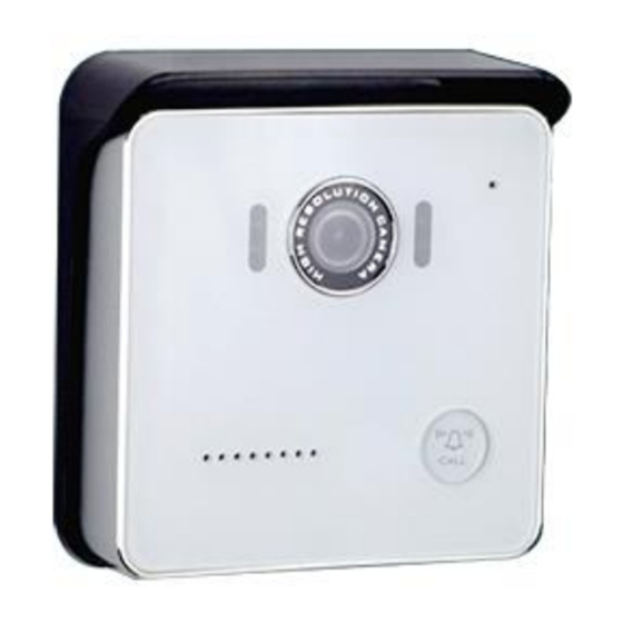
One DP-104 SIP IP Video Door Phone
One Roof for surface-mounted
One Panel for surface-mounted
One DI/DO cable
One connector
Three screws
If items are missing or damaged, notify your
Avadesign representative. Keep the carton and
packing material.
2 What Else You Need
1
One external power adaptor
Unpacking
3.
INPUT: 100-240V~ 50/60Hz 0.5A
OUTPUT: DC 12V 1.0A
One RJ-45 cable
p.s. You also can buy the power adapter from
Avadesign Technology Co., Ltd.
This is an optional item.
3 Remove two stickers
There are two layers of transparent stickers on
1
Unpacking
4.
the surface of DP-104 SIP IP video door phone.
For the voice quality and pressing the
"CALL" button smoothly, please
remove the first layer of sticker at first.
Then remove the second layer of sticker.
4 Wiring and mounting on the wall
1
Unpacking
1.
Select a location, Surface-mount the DP-104 SIP IP
video door phone at desired location.
Feed the Ethernet cable through the cable square
hole which dimensions 35 x 35mm that shown as
below.
Screw
35mm
DC 12V 1.0A Power supply
Fix the door phone on the wall using a roof or a
panel and two screws that shown as below.
82mm
120mm
35mm
or
Roof
Connect RJ-45 cable and power supply to DP-104.
Then plug into an available outlet.
RJ-45 cable
Rear view of the DP-104
The polar of power line:
Red line is for
Black line is for
Quick Installation Guide version V2.0 13-08-2015
Avadesign Technology Co. Ltd.
5 DI/DO of DP-104 instruction
This section describes how to connect door
lock/unlock control signal or alarm signal on the
printed circuit board (PCB) of DP-104 SIP IP video
door phone.
DI connects to the sensor for notifying the status, so
that the CPU to do the appropriate action.
DO connect to control device. According to the
status of device can be accessed (NC—COM) or
(NO—COM). The PCB controls the power ON/OFF
status of device by relay.
For more connection information, please refer to the
chapter 5 of the DP-104 installation & user guide.
RJ-45 Cable, connect to
the DP-104
35mm
Arrow symbol
Panel
1
2
Avadesign provides a DI/DO cable for users as below:
PIN
Apply DC
Power
DC 12V 1.0A
+
-
DP-104 JP10
PIN 1: DI+
PIN 2: DI-
PIN 3: DO Normal Close (NC)
PIN 4: DO COM
PIN 5: DO Normal Open (NO)
3
4
5
PIN 5: DO Normal Open
(NO) (black)
PIN 4: DO COM (brown)
PIN 3: DO Normal Close
(NC) (red)
PIN 2: DI- (orange)
PIN 1: DI+ (yellow)
Advertisement
Table of Contents

Related Manuals for Avadesign V-BELL DP-104

Summary of Contents for Avadesign V-BELL DP-104
- Page 1 This is an optional item. PIN 5: DO Normal Open (NO) 3 Remove two stickers Avadesign provides a DI/DO cable for users as below: There are two layers of transparent stickers on Unpacking the surface of DP-104 SIP IP video door phone.
- Page 2 The Qualia Service is the cloud service and free When you register the DP-104 door phone to SIP Unpacking Unpacking charge that provided by Avadesign Technology for server, please open your chrome browser and type the DP-104 SIP IP Video Door Phone application. an IP address.
Need help?
Do you have a question about the V-BELL DP-104 and is the answer not in the manual?
Questions and answers