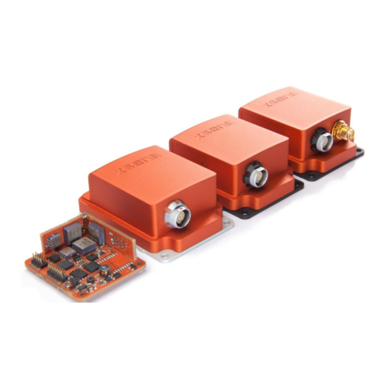
Xsens MTi 10 Series User Manual
Hide thumbs Also See for MTi 10 Series:
Table of Contents

Advertisement

Xsens Technologies B.V.
Pantheon 6a
phone
P.O. Box 559
fax
7500 AN Enschede
e-mail
The Netherlands
internet
MTi 10-series and MTi 100-series
Document MT0605P, Revision E, 17 January 2014
+31 (0)88 973 67 00
+31 (0)88 973 67 01
info@xsens.com
www.xsens.com
MTi User Manual
Xsens North America, Inc.
10557 Jefferson Blvd,
phone
Suite C
fax
CA-90232 Culver City
e-mail
USA
internet
310-481-1800
310-416-9044
info@xsens.com
www.xsens.com

Advertisement

Table of Contents
loading

Summary of Contents for Xsens MTi 10 Series

  • Page 1 MTi User Manual MTi 10-series and MTi 100-series Document MT0605P, Revision E, 17 January 2014 Xsens Technologies B.V. Xsens North America, Inc. Pantheon 6a phone +31 (0)88 973 67 00 10557 Jefferson Blvd, phone 310-481-1800 P.O. Box 559 +31 (0)88 973 67 01...
  • Page 2 Added product code, 3V3 and remark on termination resistor © 2005-2014, Xsens Technologies B.V. All rights reserved. Information in this document is subject to change without notice. Xsens, MVN, MotionGrid, MTi, MTi-G, MTx, MTw, Awinda and KiC are registered trademarks or trademarks of Xsens Technologies B.V. and/or its parent, subsidiaries and/or affiliates in The Netherlands, the USA and/or other countries.
  • Page 3: Table Of Contents

    MTi 100-series filter profiles ....................19 3.3.6 MTi-G-700 filter profiles ...................... 20 OUTPUT SPECIFICATION ........................22 ......................23 VERVIEW OF DATA OUTPUTS 4.1.1 MTData2 output in XBus protocol ..................23 4.1.2 NMEA protocol ........................24 Document MT0605P.E © Xsens Technologies B.V. MTi User Manual...
  • Page 4 MTi triggers external devices (Interval Transition Measurement) ........... 58 5.5.4 Clock synchronization (Clock Bias Estimation) ............... 59 5.5.4.1 Clock Bias Estimation from GPS ................... 59 5.5.5 StartSampling ........................59 5.5.6 Combining synchronization functions ................... 60 Document MT0605P.E © Xsens Technologies B.V. MTi User Manual...
  • Page 5 ..........................76 AINTENANCE CE D ................77 ECLARATION OF ONFORMITY FOR THE DEVICES FCC D ................78 ECLARATION OF ONFORMITY FOR THE DEVICES ........................79 ARRANTY AND LIABILITY ........................79 USTOMER UPPORT Document MT0605P.E © Xsens Technologies B.V. MTi User Manual...
  • Page 6: References

    “MT Low-Level Communication Protocol Documentation.pdf”, document ID [LLCP] MT0101P “MT Manager User Manual.pdf”, document ID MT0216P [MTM] [XDA_DOC] XDA doxygen HTML documentation. Found in Xsens folder structure “MTi Technical Datasheet.pdf”, document ID MT0503P [MTI_TD] Document MT0605P.E © Xsens Technologies B.V. MTi User Manual...
  • Page 7: Introduction

    The MTi product range is divided in two series, the MTi 10-series and the MTi 100-series. The MTi 10- series is Xsens’ entry level model with robust accuracy and a limited range of IO options. The 100- series is a revolutionary new class of MEMS IMU’s, orientation and position sensor modules offering unprecedented accuracies and a wide array of IO interfaces.
  • Page 8: Mti 100-Series

    2.2.3 MTi-200 VRU The MTi-200 VRU is a 3D vertical reference unit (VRU) and this unit too runs the Xsens sensor fusion algorithm from the MTi-G-700 and MTi-300. The difference between the data of the MTi-300 and MTi- 200 is that yaw is unreferenced, though the yaw is still much better than just integrating rate of turn.
  • Page 9: Identifying Device Functionality Using The Unique Device Identifier

    Identifying device functionality using the unique Device Identifier Each Xsens product is marked with a unique serial device identifier referred to as the DeviceID. The DeviceID is categorized per MTi product configuration in order to make it possible to recognize the MTi (and thus its functionality and interface) by reviewing the DeviceID.
  • Page 10: Evolution Of Mti Products

    2.3 Evolution of MTi products The MTi 10-series and MTi 100-series are Xsens 4 generation products, building on knowledge and products from over a decade. They may be designated as MkIV MTi’s. In source code or software, this can be Mk4.
  • Page 11: Overview Mti Development Kit

    MT Magnetic Field Mapper Documentation [MT0202P]  XDA doxygen HTML API documentation NOTE: the most recent version of the software, source code and documentation can always be downloaded on the support section of www.xsens.com/en/support. Document MT0605P.E © Xsens Technologies B.V. MTi User Manual...
  • Page 12: Installation

    To prevent this, the sleeve of the Fischer connector may be locked with the ring at the connector. Xsens has tested a set of vibration dampeners on the MTi. Vibration dampeners are low-profile rubber cylinders that allow the MTi to be mounted on an object without a direct metal to metal connection that transduces vibrations from the object to the MTi.
  • Page 13: Magnetic Materials And Magnets

    The effect of the strong alternating fields is to remove any magnetized (aligned) domains in the object. When degaussing, make sure the MTi is not attached to the object. This type of disturbance is non-deterministic. Document MT0605P.E © Xsens Technologies B.V. MTi User Manual...
  • Page 14: Typical User Scenarios

    The XBus low-level protocol is described in high detail in the Low Level Communication Protocol: [LLCP]. The hardware driver of the USB interface for Linux can be found on http://github.com/xsens/xsens_mt. The driver is also included in Linux kernel 3.9 and higher.
  • Page 15: Getting Started With The Mt Manager

    With the MT Manager, it is possible to apply a configuration profile to multiple MTi’s. This allows system integrators to configure MTi’s fast and accurate. Applies to: Windows PC platform Please refer to the MT Manager User Manual [MTM] for more information on this topic Document MT0605P.E © Xsens Technologies B.V. MTi User Manual...
  • Page 16: Using The Software Development Kit (Sdk)

    2.6.3 Using the Software Development Kit (SDK) This chapter gives an introduction to the Xsens Device API (XDA). It serves as a starting point for members of a software development department interested in assessing the basis of the SDK and knowing about the background considerations.
  • Page 17 MTi into Euler angles. The C API exposes all possible functions that could be supported by an Xsens device. As such, a certain functionality implemented in devices is accessible by a function call that takes at least an XsDevice Object as a parameter.
  • Page 18: Direct Low-Level Communication With Mti

    Migration from MT SDK 3.3 (CMT) Programmers familiar with using the CMT interface from the MT SDK 3.x and lower (Xsens’ interface for legacy MTi products) will find that changes need to be made in order to work with the new XDA.
  • Page 19: Terms Of Use Mt Software Suite

    Component EULA/SLA Guidelines MT Manager EULA For use with Xsens products only Not allowed to re-distribute Not allowed to reverse engineer Not allowed to modify Serial key required MT SDK For use with Xsens products only Allowed to re-distribute “as is”...
  • Page 20: Mti System Overview

    3.2 Xsens Kalman Filter (XKF3i) for MTi 10-series The orientation of the MTi 10-series is computed by Xsens Kalman Filter. XKF3i uses signals of the rate gyroscopes, accelerometers and magnetometers to compute a statistical optimal 3D orientation estimate of high accuracy with no drift for both static and dynamic movements.
  • Page 21: Using The Earth Magnetic Field To Stabilize Yaw

    The different filter profiles are divided in several types of motion and are discussed below. Number Name Magnetometer Product • • General 30-AHRS • • High_mag_dep 30-AHRS • • Dynamic 30-AHRS • • Low_mag_dep 30-AHRS • VRU_general 30-AHRS, 20-VRU Document MT0605P.E © Xsens Technologies B.V. MTi User Manual...
  • Page 22 Every application is different and although example applications are listed above, results may vary from setup to setup. It is recommended to reprocess recorded data with different filter profiles in MT Manager to determine the best results in your specific application. Document MT0605P.E © Xsens Technologies B.V. MTi User Manual...
  • Page 23: Xsens Sensor Fusion Algorithm For Mti 100-Series

    3.3 Xsens sensor fusion algorithm for MTi 100-series 3.3.1 MTi 100-series filter The Xsens sensor fusion algorithm in the MTi 100-series has several advanced features. It can handle a multitude of data channels, to incorporate GPS and barometer data as well. 3.3.2...
  • Page 24: Mti-G-700 Filter Profiles

    In the Automotive filter profile, yaw is locked (e.g. gyro bias will be estimated and yaw will not change), when GPS indicates that there is no movement. This is useful when standing still, as gyro bias would otherwise induce a yaw drift. Document MT0605P.E © Xsens Technologies B.V. MTi User Manual...
  • Page 25 Every application is different and although example applications are listed above, results may vary from setup to setup. It is recommended to reprocess recorded data with different filter profiles in MT Manager to determine the best results in your specific application. Document MT0605P.E © Xsens Technologies B.V. MTi User Manual...
  • Page 26: Output Specification

    Performance specifications on orientation, position and sensor data can be found in section 4.3. Before going into these sections, it is useful to read section 4.1.2, which explains the various coordinate systems and position representations. Document MT0605P.E © Xsens Technologies B.V. MTi User Manual...
  • Page 27: Overview Of Data Outputs

    Maximum frequencies may differ on the chosen combination of outputs. Availability and frequency of outputs may differ between onboard processing and processing in XDA, as SCR or delta_q/delta_v is needed for processing data. Document MT0605P.E © Xsens Technologies B.V. MTi User Manual...
  • Page 28: Nmea Protocol

    Quaternion, Acceleration, Rate of Turn, Magnetic Field, Temp. Bit 7 $HCMTW Temperature Bit 8 $HEHDT True Heading Bit 9 $HEROT Rate of Turn Bit 10-15 Reserved Reserved for future string types Document MT0605P.E © Xsens Technologies B.V. MTi User Manual...
  • Page 29: Coordinate Systems

    In the MTi, this interval is 2.5 ms (400 Hz) by default. The values dq and dv are always represented in the same coordinate system as calibrated inertial data and magnetic field data (see section 4.2.1), which can be (S) or (O). Document MT0605P.E © Xsens Technologies B.V. MTi User Manual...
  • Page 30: Orientation Data

    MTi-G should point to the front of the vehicle, in NWU and NED coordinate systems that means that the x-axis of the MTi-G should point to the front of the vehicle. IEEE Standard for Inertial Systems Terminology Document MT0605P.E © Xsens Technologies B.V. MTi User Manual...
  • Page 31: Velocity Data

    World Magnetic Model (Xsens uses WMM 2010-2015) of the earth’s magnetic field as a function of latitude and longitude. The MTi accepts a setting of the declination value. This is done by setting the position in the MT Manager, SDK or by direct communication with the sensor.
  • Page 32 MTi-G over the curved Earth surface if the MTi-G has a velocity. Therefore, we can work with a local linearized tangent plane without making any significant errors. Document MT0605P.E © Xsens Technologies B.V. MTi User Manual...
  • Page 33 “geoid”. The value of vertical deviation (or also called Ellipsoid vertical deflection) can be a small fraction of a degree. For the continental US, the maximum vertical deviation can be about +/- 0.01 degrees. Document MT0605P.E © Xsens Technologies B.V. MTi User Manual...
  • Page 34: Orientation Performance Specification

    Depending on the specific situation this can lead to large errors or even instability of the filter. Take care to select the correct filter profile. If you are uncertain, do not hesitate to contact Xsens or your local distributor. ...
  • Page 35: Position And Velocity Performance Specification (Mti-G-700)

    The MTi-G-700 has the ability to output position. The performance highly depends on the GPS availability, placement of the GPS antenna etc. The table below states the position and velocity accuracy according to Xsens’ reference trajectories, as explained in [MTI_TD].
  • Page 36: Quaternion Orientation Output Mode

    (i.e. pitch approaches ±90). In practice this means roll and pitch is not defined as such when pitch is close to ±90 deg. This singularity is in no way present in the quaternion or rotation matrix output mode. Document MT0605P.E © Xsens Technologies B.V. MTi User Manual...
  • Page 37: Euler Angles Orientation Output Mode

    S are found in the columns of the matrix, so col 1 is X expressed in L etc. A rotation matrix “yaw” is also known as: “heading”, “pan” or “azimuth” “pitch” is also known as: “elevation” or “tilt” “roll” is also known as: “bank” Document MT0605P.E © Xsens Technologies B.V. MTi User Manual...
  • Page 38 ] = [ ���� �� �� �� �� �� �� �� �� �� �� �� �� �� �� �� �� �� �� �� ] = [ ���� �� ℎ �� �� �� �� Document MT0605P.E © Xsens Technologies B.V. MTi User Manual...
  • Page 39: Sensor Data Performance Specification

    In-run bias stability [deg/h] Bandwidth (-3dB) [Hz] [deg/s/√Hz] Noise density 0.03 0.05 0.01 0.015 g-sensitivity (calibrated) [deg/s/g] 0.006 0.02 0.003 0.015 Non-orthogonality [deg] 0.05 0.05 Non-linearity [% FS] 0.03 0.01 A/D resolution [bits] Document MT0605P.E © Xsens Technologies B.V. MTi User Manual...
  • Page 40: Accelerometers And Magnetometer

    The MTi 10-series and MTi 100-series use the same accelerometers and magnetometer. The output of the magnetometer is in arbitrary units (a.u.), one a.u. is the magnetic field strength during calibration at Xsens’ calibration lab. This is approximately 40 uT. An accelerometer range of 15g is available as well.
  • Page 41: Gps Receiver

    The MTi-G-700 is the only MTi that features a GPS receiver. It requires an active antenna, which is delivered with the Development Kit and can be ordered separately from Xsens as well. It is possible to use a different antenna that better suits your application.
  • Page 42: Built-In Self-Test

    A passed self-test will result in a valid self-test flag in the status byte. Because the self-test influences the sensor data, the self-test is only available in Config mode. For more information, refer to [LLCP], function RunSelftest. Document MT0605P.E © Xsens Technologies B.V. MTi User Manual...
  • Page 43: Test And Calibration Certificate

    4.8 Test and Calibration Certificate Each MTi is accompanied by an individual Test and Calibration Certificate. This certificate states the calibration values determined during the calibration of the MTi at Xsens’ calibration facilities. The values are explained here in short: The “IMU specifications”...
  • Page 44: Sensors Data Outputs

    The basic indicative parameters in the above model of your individual MTi can be found on the MT Test and Calibration Certificate and in the MT Manager (MT Settings dialog). Document MT0605P.E © Xsens Technologies B.V. MTi User Manual...
  • Page 45: Calibrated Delta_Q And Delta_V Outputs

    Calibrated data has been going through Strapdown Integration and Inverse Strapdown Integration. 4.9.4 Free acceleration Free acceleration (Data ID 0x4030) is the acceleration of which gravity is deducted. Output is in m/s Document MT0605P.E © Xsens Technologies B.V. MTi User Manual...
  • Page 46: Uncalibrated Raw Output Mode

    Uncalibrated raw output mode The MTi can output sensor component readout (SCR), i.e. digitized voltages of all sensors, before they are filtered or calibrated using Xsens’ proprietary firmware and calibration parameters. These sensors are the gyroscopes (rate of turn), accelerometers (acceleration), magnetometer (magnetic field), barometer (static pressure) and temperatures (gyroscope temperatures and a general temperature sensor).
  • Page 47: Legacy Output Messages

    4.10 Legacy output messages The MTi 10-series and MTi 100-series are Xsens’ 4 generation MTi (MkIV). The 2 and 3 generation products have been released in 2005 and 2008. The 4 generation can be distinguished by their aluminium casing (or orange PCB if you are using an OEM). A photo of the 4 generation MTi can be found on the cover of this manual.
  • Page 48: Reset Of Output Or Reference Co-Ordinate Systems

    ∙ ( 1 0 0 ) ⟩ ��′ �� �� �� = ( 0 0 1 ) ��′ �� �� �� �� = ⟨ �� × �� ⟩ ��′ ��′ ��′ Document MT0605P.E © Xsens Technologies B.V. MTi User Manual...
  • Page 49 NWU is the reference coordinate system that used to be the default up to the third generation MTi and MTi-G. In order to configure the MTi to output in the NWU local frame, apply the following rotation matrix in RotLocal. RotLocal −1 0 ������ Document MT0605P.E © Xsens Technologies B.V. MTi User Manual...
  • Page 50 R, and NOTE: when applying SS’R and outputting dq/dv only will result in double applying of SS’R when outputting orientation from XDA. To prevent this, output orientation directly from the MTi. Document MT0605P.E © Xsens Technologies B.V. MTi User Manual...
  • Page 51: Timestamp And Packet Counter Output

    As the moment of setting the time is different than the time the MTi receives the message and sets the starting point, a message is implemented to adjust Time UTC in ticks of 0.1 ms. See [LLCP] for more information about the messages SetUTCTime and AdjustUTCTime. Document MT0605P.E © Xsens Technologies B.V. MTi User Manual...
  • Page 52: Status Byte

    If set an out of range magnetic field on the Y axis is detected Clipflag Mag Z If set an out of range magnetic field on the Z axis is detected 17:18 NoVelocityUpdate status Document MT0605P.E © Xsens Technologies B.V. MTi User Manual...
  • Page 53 GeneralMag filter profile that continues to use magnetometers) 001: Coasting mode (GPS has been lost <60 sec ago) 011: With GPS (default mode of MTi-G-700) 26:31 Reserved Reserved for future use Document MT0605P.E © Xsens Technologies B.V. MTi User Manual...
  • Page 54: Basic Communication

    Config State or Measurement State is to use the GoToConfig or GoToMeasurement messages. The eMTS data is required to be able to later process the data by Xsens software to calculate calibrated inertial data values as well as estimating orientation etc.
  • Page 55: Messages

    The checksum value of the message should be included in the summation. Document MT0605P.E © Xsens Technologies B.V. MTi User Manual...
  • Page 56: Message Usage

    To change the baud rate you must add the baud rate in the data field of the sending message: Set the output mode: Sending message: SetBaudrate = 0xFA 0xFF 0x18 0x01 BR CS (hexadecimal values) Receiving message (= Acknowledge): SetBaudrateAck = 0xFA 0xFF 0x19 0x00 0xE8 (hexadecimal values) Document MT0605P.E © Xsens Technologies B.V. MTi User Manual...
  • Page 57: Common Messages

    Valid in Measurement State The MTData2 message contains output data according the current OutputConfiguration. Unlike the legacy MTData message an MTData2 message does not have to contain all configured output all the Document MT0605P.E © Xsens Technologies B.V. MTi User Manual...
  • Page 58: Communication Timing

    When the MTi is in Measurement State, the internal processor core continuously controls a signal processing pipeline, roughly according to the above diagram. Outputting data can be triggered by the device internal clock, or by external software triggers (polling), or hardware triggers. For more Document MT0605P.E © Xsens Technologies B.V. MTi User Manual...
  • Page 59 1. Internal acquisition, calculation time and message generation (signal processing duration) 2. Serial transmission time Thanks to the system architecture of the Xsens sensor fusion algorithm, the signal processing duration is independent of the filter profile. Using a multi-core processing unit, it is possible to bring...
  • Page 60 When the MTi is used with the USB cable, much of the timing depends on the scheduling of the host (e.g. Windows) as the host needs to poll data from the USB devices. For real time interfaces, a serial interface (RS232, RS422 or RS485) is recommended. Document MT0605P.E © Xsens Technologies B.V. MTi User Manual...
  • Page 61: Triggering And Synchronization

    Next to let the MTi send data to the computer, it is also possible to incorporate a trigger indication in the MTData2 packet (Status Word). The data will not be affected by the trigger indication; the data is marked with the pulse received. Document MT0605P.E © Xsens Technologies B.V. MTi User Manual...
  • Page 62: Mti Triggers External Devices (Interval Transition Measurement)

    MTI cable you can connect directly to the appropriate pin of the Molex header. NOTE: Always check if the input voltage levels and the input impedance of the external device matches the SyncOut specifications. Document MT0605P.E © Xsens Technologies B.V. MTi User Manual...
  • Page 63: Clock Synchronization (Clock Bias Estimation)

    It is possible to delay the “First sample received”, and with that the entire data output, with up to 0.65536 seconds. For example, setting a delay of 6810 us (6.81 ms) will output data at exactly 10 ms after the external pulse has been received. Document MT0605P.E © Xsens Technologies B.V. MTi User Manual...
  • Page 64: Combining Synchronization Functions

    If you need orientation at a different rate than the camera images, you can send the Interval Transition Measurement (SyncOut) at a SkipFactor and with an offset to give the camera time to make the picture. Document MT0605P.E © Xsens Technologies B.V. MTi User Manual...
  • Page 65: Internal Clock Accuracy

    Note that there is no terminating resistor in the MTi with RS422/RS485 communication. Should communication problems arise, terminate the connection either at the application side or alternatively close to the MTi. Document MT0605P.E © Xsens Technologies B.V. MTi User Manual...
  • Page 66: General Definitions For Binary Data

    However, it is not possible to have communication on both the serial and USB interfaces simultaneously. Therefore, the MTi wakes up as a serial device, unless USB is detected. When a USB interface is detected, the communication will be done via that USB interface. Document MT0605P.E © Xsens Technologies B.V. MTi User Manual...
  • Page 67: Physical Specifications

    Please note that efficiency of the power input stage will decrease with increasing supply voltage. If an alternative power supply is used check if it can supply these peak currents. Do not use a power supply if the peak supply current is lower than stated. Document MT0605P.E © Xsens Technologies B.V. MTi User Manual...
  • Page 68: Alternative 3V3 Power Supply

    VCC (4.5-34V) or the alternative 3V3 power. When there is a voltage applied both to the standard VCC and the alternative 3V3, the MTi will not start up and may be damaged. Refer to section 6.3 for the pin configuration, including 3V3. Document MT0605P.E © Xsens Technologies B.V. MTi User Manual...
  • Page 69: Mechanical And Electrical Interface Specifications

    Connect the cable to the MTi and the USB cable to any USB port. Under Windows 7 and Windows XP, the Xsens USB driver will be automatically installed if not already installed. In order to lock the CA- MP-MTi to the casing (this will prevent vibration of the push-pull sleeve to be transferred to the casing and MEMS sensors), screw the round nut clockwise.
  • Page 70 For this purpose a helix antenna is recommended. In contrast to helix antennas, patch antennas require a ground plane for operation. Helix antennas can be designed for use with or without a ground plane. Document MT0605P.E © Xsens Technologies B.V. MTi User Manual...
  • Page 71: Oem Connections Overview

    14_14 Reserved Pin 1 and 10 of the 10-pins header and pin 1 and pin 14 of the 14-pins header are labelled on the PCB. 3V3 available from hardware version 2.0 Document MT0605P.E © Xsens Technologies B.V. MTi User Manual...
  • Page 72 14-pins 1.27 mm pitch Molex 90635-1143 1392991 These connectors can be connected to ribbon cables without tools to make a cable like below. On the right is an application of such a cable. Document MT0605P.E © Xsens Technologies B.V. MTi User Manual...
  • Page 73: Additional Interface Specifications

    High value: > 2.9 V ClockSync Low value: 0 - 0.8 V Input resistance: ~100 kΩ 0-20V High value: 2.5 -20 V For the descriptions of the synchronization functions, see [LLCP]. Document MT0605P.E © Xsens Technologies B.V. MTi User Manual...
  • Page 74: Using The Mti Mkiv With An External Usb Converter

    Using the MTi MkIV with an external USB converter Xsens offers a cable to use the MTi with USB and SyncIn. This cable also offers an interface via a virtual COM-port instead of WinUSB. The following cables are available in Xsens’ webshop (http://shop.xsens.com):...
  • Page 75: Housing Mechanical Specifications

    Environmental protection of the housing All encased MTi’s are designed to withstand usage in application where dust and occasional water splashing can be expected. However, Xsens in house testing has confirmed that the casing and connector can withstand temporary environmental circumstances equivalent to Protection Classification IP67 (sealed against dust, 30 minutes immersion at depth of 1 m).
  • Page 76: Mti 10-Series Technical Drawing

    6.4.4 MTi 10-series technical drawing CAD drawings (STEP) are available at request via sales@xsens.com Document MT0605P.E © Xsens Technologies B.V. MTi User Manual...
  • Page 77: Mti 100-200-300 Technical Drawing

    6.4.5 MTi 100-200-300 technical drawing CAD drawings (STEP) are available at request via sales@xsens.com Document MT0605P.E © Xsens Technologies B.V. MTi User Manual...
  • Page 78: Mti-G-700 Technical Drawing

    6.4.6 MTi-G-700 technical drawing CAD drawings (STEP) are available at request via sales@xsens.com Document MT0605P.E © Xsens Technologies B.V. MTi User Manual...
  • Page 79: Mti-Oem Technical Drawing

    6.4.7 MTi-OEM technical drawing CAD drawings (STEP) are available at request via sales@xsens.com Document MT0605P.E © Xsens Technologies B.V. MTi User Manual...
  • Page 80: Important Notices

    7.3 Maintenance The MTi will not require any maintenance if properly used (see also section 7.1 and 7.2). However, if the Motion Tracker is not functioning according to the specifications please contact Xsens or your local distributor (www.xsens.com/support). Document MT0605P.E ©...
  • Page 81: Ce Declaration Of Conformity For The Mt Devices

    7.4 CE Declaration of Conformity for the MT devices We, Xsens Technologies BV, of Pantheon 6a 7521 PR Enschede, The Netherlands declare under our sole responsibility that our products: MTi-10-#A#G# (MTi-10-2A5G4, MTi-10-2A5G0, MTi-10-4A5G4, MTi-10- 4A5G0, MTi-10-6A5G4, MTi-10-6A5G0, MTi-10-2A8G4, MTi-10-2A8G0, MTi-10-4A8G4, MTi-10-4A8G0, MTi-10-...
  • Page 82: Fcc Declaration Of Conformity For The Mt Devices

    7.5 FCC Declaration of Conformity for the MT devices We, Xsens Technologies BV, of Pantheon 6a 7521 PR Enschede, The Netherlands declare under our sole responsibility that our products: MTi-10-#A#G# (MTi-10-2A5G4, MTi-10-2A5G0, MTi-10-4A5G4, MTi-10- 4A5G0, MTi-10-6A5G4, MTi-10-6A5G0, MTi-10-2A8G4, MTi-10-2A8G0, MTi-10-4A8G4, MTi-10-4A8G0, MTi-10-...
  • Page 83: Warranty And Liability

    7.7 Customer Support Xsens is glad to help you with any questions you may have about the MTi, or about the use of the technology for your application. Please use the FAQ, contact Xsens’ distributor or if you are a direct customer of Xsens our Customer Support: ...
  • Page 84 X-ON Electronics Largest Supplier of Electrical and Electronic Components Click to view similar products for manufacturer: xsens Other Similar products are found below : CA-USB6-MTI CA-USB4-MTI CA-USB2-MTI CA-USB-MTI CA-MP2-MTI...

Table of Contents