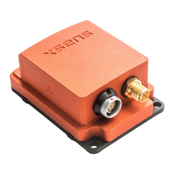
Table of Contents REFERENCES ..........................3 XSENS HELP CENTER AND USER COMMUNITY ..............4 INTRODUCTION ..........................5 ..........................5 SERIES 3.1.1 MTi-30 AHRS ........................5 3.1.2 MTi-20 VRU ........................5 3.1.3 MTi-10 IMU ........................5 100- ........................... 6 SERIES 3.2.1 MTi-G-710 GNSS/INS .......................
[MTM] “MT Manager User Manual.pdf”, document ID MT0216P [XDA_DOC] XDA doxygen HTML documentation. Found in Xsens folder structure [MTI_1] “MTi 1-series Datasheet.pdf”, document ID MT0512P Note: The latest available documentation can be found in your MT Software Suite installation folder or via the following link: https://xsens.com/xsens-mti-documentation...
(registration required). The user community is the place to ask questions. Answers may be given by other users or by Xsens employees. The response time in the user community is significantly shorter than the response time at Xsens support.
The MTi product range is divided in three series, the MTi 1-series, the MTi 10-series and the MTi 100- series. The MTi 10-series is Xsens’ entry level model with robust accuracy and a limited range of IO options. The 100-series is a new class of MEMS IMU’s, orientation and position sensor modules offering unprecedented accuracies and a wide array of IO interfaces.
3.2.3 MTi-200 VRU The MTi-200 VRU is a 3D vertical reference unit (VRU) and this unit runs the Xsens sensor fusion algorithm from the MTi-300 as well. The difference between the data of the MTi-300 and MTi-200 is that yaw is unreferenced, though the yaw is still much better than just integrating rate of turn when using the gyro bias estimation techniques available.
Identifying device functionality using the unique Device Identifier Each Xsens product is marked with a unique serial device identifier referred to as the DeviceID. The DeviceID is categorized per MTi product configuration in order to make it possible to recognize the MTi (and thus its functionality and interface) by reviewing the DeviceID.
Test and Calibration certificate MT Software Suite available via www.xsens.com/setup Xsens MTi USB driver MT Manager GUI for Linux and Windows MT Software Development Kit (MT SDK) for multiple OS XsensDeviceApi.DLL, 32-bit and 64-bit (Windows) ...
Firmware Updater User Manual [FU0100P] Firmware Updater (Windows) NOTE: the most recent version of the software, source code and documentation can always be downloaded on www.xsens.com/mt-software-suite. Links to documentation can be found on BASE: https://base.xsens.com/hc/en-us/articles/207003759 3.5 Installation 3.5.1 Transient accelerations The 3D linear accelerometers in the MTi are primarily used to estimate the direction of gravity to obtain a reference for attitude (pitch/roll).
MTi. Xsens has tested a set of vibration dampeners on the MTi. Vibration dampeners are low-profile rubber cylinders that allow the MTi to be mounted on an object without a direct metal to metal connection that transduces vibrations from the object to the MTi.
The Xbus low-level protocol is described in high detail in the Low Level Communication Protocol: [LLCP]. The hardware driver of the USB interface for Linux can be found on https://github.com/xsens/xsens_mt. The driver is also included in Linux kernel 3.9 and higher.
3.6.3 Using the Software Development Kit (SDK) This chapter gives an introduction to the Xsens Device API (XDA). It serves as a starting point for system integrators interested in assessing the basis of the SDK and knowing about the background considerations.
Internally the Xsens host software is implemented using an object oriented approach in which the functionality is only implemented in subclasses, see schematic below. Figure 7: Functionality implementation for specific products It is important for the developer to use only functions supported by the connected device. During run time, calling an unsupported function will generate an error status in line with the normal error handling framework.
Allowed to re-distribute “as is” or embed in programs Not allowed to reverse engineer Allowed to execute, reproduce, modify and compile (modified) source code to use with Xsens products only Not allowed to modify DLL Include License Agreement with distribution For use with Xsens products only Allowed to re-distribute “as is”...
A correct calibration of the sensor components inside the MTi is essential for an accurate output. The quality and importance of the calibration are of highest priority and so each Xsens’ MTi is calibrated and tested by subjecting each product to a wide range of motions and temperatures.
The XKF3i algorithm not only computes orientation, but also keeps track of variables such as sensor biases or properties of the local magnetic field (magnetic field: MTi-30 AHRS only). For this reason, the orientation output may need some time to stabilize once the MTi is put into measurement mode. Time to obtain optimal stable output depends on a number of factors.
4.3 Xsens sensor fusion algorithm for MTi-G-710 The Xsens sensor fusion algorithm in the MTi-G-710 has several advanced features. It can handle a multitude of data channels, to incorporate GNSS and barometer data as well.
This enables the user to adjust the u-blox receiver platform to match the dynamics of an application. The setting influences the estimates of Position and Velocity and therefore it affects the behaviour of the Xsens filter output. Currently, only the Portable (default) and Airborne (<4g) platforms are supported.
With the default ENU (L) coordinate system, Xsens yaw output is defined as the angle between East (X) and the horizontal projection of the sensor roll axis (x), positive about the local vertical axis (Z) following the right hand rule.
Magnetic North and True North (known as the magnetic declination) varies depending on the location on earth and can be roughly obtained from the World Magnetic Model (Xsens uses WMM 2010-2015) of the earth’s magnetic field as a function of latitude and longitude. The MTi accepts a setting of the declination value.
Depending on the specific situation this can lead to large errors or even instability of the filter. Take care to select the correct filter profile. If you are uncertain, do not hesitate to contact Xsens or your local distributor. ...
The MTi-G-710 has the ability to give position and velocity output. The table below states the position and velocity accuracy according to Xsens’ reference trajectories. Table 8: Position and velocity performance specifications (MTi-G-710) Parameter Specification Horizontal (SBAS) 1.0 m (1σ STD)
The MTi-G-710 is the only MTi that features a GNSS receiver. It requires an active antenna, which is delivered with the Development Kit and can be ordered separately from Xsens as well. It is possible to use a different antenna that better suits your application.
(electronic Motion Tracker settings). It is digitally signed by a Test Person and states the calibration values determined during the calibration of the MTi at Xsens’ calibration facilities. For reference, the values can be read by connecting the MTi to MT Manager and navigating to MT Settings –...
The MTi can give a sensor component readout output (SCR, DataID 0xA010 for the sensors data and 0xA020 for the gyroscope temperatures), i.e. digitized voltages of all sensors, before they are filtered or calibrated using Xsens’ proprietary firmware and calibration parameters. These sensors are the gyroscopes (rate of turn), accelerometers (acceleration), magnetometer (magnetic field), barometer (static pressure) and temperatures (gyroscope temperatures and a general temperature sensor).
6.1 Communication Timing For many applications it is crucial to know exactly the various delays and latencies in a system. This has been extensively discussed in https://base.xsens.com/hc/en-us/articles/209306289. 6.2 Triggering and synchronization In case multiple systems are used during a measurement it is important to have the measurement data synchronized between the systems.
Pin configuration casing receptacle CA-USB-MTi Connect the cable to the MTi and the USB cable to any USB port. Under Windows 7, the Xsens USB driver will be automatically installed if not already installed. In order to lock the CA-USB-MTi to the casing (this will prevent vibration of the push-pull sleeve to be transferred to the casing and MEMS sensors), screw the round nut clockwise.
AWG28 Shielding 7.3.1.3 GNSS Antenna The MTi-G-710 requires an active patch antenna that can be connected to SMA connector in the front panel of the MTi-G-710. See also https://base.xsens.com/hc/en-us/articles/209434509. 7.3.2 OEM connections overview 7.3.2.1 Power and data All MTi’s are available as OEM-board as well. The connection from the OEM board to the push-pull connector of the encased version is a flexible PCB, which has put to vibration test according to MIL-STD 202.
7.3.2.2 GNSS receiver The MTi-G-710 needs an active antenna. The connection on the OEM board of the MTi-G-710 is done with an u.FL miniature coax. See also https://base.xsens.com/hc/en-us/articles/209434509. 7.3.2.3 Connecting with the OEM board Connecting to the OEM board is possible by using sockets with a pitch of 1.27 mm. Notable manufacturers are Samtec, Molex and Hirose.
Using the MTi Mk5 with an external USB converter Xsens offers a cable to use the MTi with USB and SyncIn. This cable also offers an interface via a virtual COM-port instead of WinUSB. The cables in Table 26 can be ordered from the Xsens’ webshop (https://shop.xsens.com).
OR OTHERWISE. Xsens shall have no liability for delays or failures beyond its reasonable control. 8.7 Customer Support Xsens is glad to help you with any questions you may have about the MTi, or about the use of the technology for your application. The fastest way is Xsens’ Help Center, where engineers and other Xsens users meet.
Need help?
Do you have a question about the MTi-30 AHRS and is the answer not in the manual?
Questions and answers