
Related Manuals for FiberHome AN6001-G16


Summary of Contents for FiberHome AN6001-G16
- Page 1 AN6001-G16 Optical Line Terminal Equipment User Manual FiberHome Telecommunication Technologies Co., Ltd. September 2019...
- Page 3 Please contact your local sales representative, service representative or distributor for any help needed at the contact information shown below. Fiberhome Telecommunication Technologies Co., Ltd. Address: No. 67, Guanggu Chuangye Jie, Wuhan, Hubei, China Zip code: 430073...
- Page 5 Legal Notice are trademarks of FiberHome Telecommunication Technologies Co., Ltd. (Hereinafter referred to as FiberHome) All brand names and product names used in this document are used for identification purposes only and are trademarks or registered trademarks of their respective holders.
-
Page 7: Table Of Contents
Contents Documentation Guide ..................1 Product Introduction..................3 Product Appearance .................4 Product Positioning................5 Power Supply Mode................5 Product Highlights...................7 Product Specification ..................9 List of Functions and Features ............10 Major Technical Specifications ............12 Web-Based Configuration Guide ..............14 Configuring Device Management Parameters........15 Logging into the Web Configuration GUI Locally ......20 Introduction to the Web Configuration GUI........22 Device Management...............23 5.4.1... - Page 8 5.6.2 Adding VLAN to Ports ............38 5.6.3 Multicast Service ..............40 5.6.4 Voice Service..............46 QinQ....................51 5.7.1 QinQ Profile..............52 5.7.2 OLT QinQ Domain ............53 5.7.3 Binding a QinQ Profile............55 5.7.4 Attaching / Detaching a Domain to / from an ONU....56 5.7.5 Attaching / Detaching a Domain to / from a PON Port ..58 Management VLAN ................60 5.8.1 Management VLAN ............60...
-
Page 9: Documentation Guide
Documentation Guide Document Orientation This manual aims to instruct users in configuring services of the AN6001-G16 through the Web GUI. To help users better understand and implement service configurations, we provide basic configuration rules, network planning, Web GUI- based operation procedures and typical service examples in this manual. - Page 10 AN6001-G16 Optical Line Terminal Equipment User Manual Related Documentation Applied to Document AN6001-G16 Optical Line Terminal Equipment Network planning phase Product Overview Network deployment phase / network AN6001-G16 Optical Line Terminal Equipment Quick maintenance phase Installation Guide AN6001-G16 Optical Line Terminal Equipment CLI...
-
Page 11: Product Introduction
Product Introduction Product Appearance Product Positioning Power Supply Mode Version: A... -
Page 12: Product Appearance
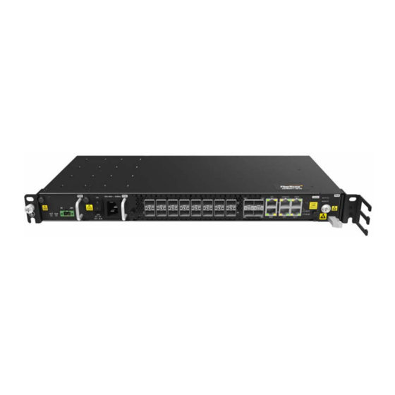
AN6001-G16 Optical Line Terminal Equipment User Manual Product Appearance The AN6001-G16 is a small-sized cassette-shaped optical line access equipment developed by FiberHome. It is designed with pluggable modularized power cards, fan unit, core switch service cards and optical modules for easy installation, deployment and maintenance. -
Page 13: Product Positioning
The AN6001-G16 provides three power supply schemes: dual-DC, dual-AC and DC-AC hybrid schemes. All these schemes support 1+1 redundancy backup. AC Power Supply The AN6001-G16 supports 110 V / 220 V active-standby AC power supply featuring lightning protection, filtering, lightning protection failure alarm and input voltage detection. - Page 14 The AN6001-G16 supports -48 V active-standby DC power supply featuring voltage monitoring, failure alarm reporting and protection switching. The table below describes the model numbers, appearance and input / output specifications of the PDPs for the DC power supply scheme of the AN6001-G16. Item PDP260B...
-
Page 15: Product Highlights
Product Highlights High-density Modularized Integration 1U high, designed with modularized core switch service card, fan card and power card for easy installation and replacement. Supports 16 GPON ports, two 10GE uplink ports (SFP+), two GE uplink optical ports (SFP) and two GE uplink electrical ports to allow access of 1024 ONUs. Flexible Deployment Supports mounting in 19-inch / 21-inch cabinets or outdoor cabinets and mounting on the wall. - Page 16 AN6001-G16 Optical Line Terminal Equipment User Manual Supports IGMP Snooping and Proxy, IGMPv3 and MLDv2 source address filtering, and rate control for multicast packets. Supports STP/MSTP, link aggregation, DHCP and port isolation. Supports both IPv4 and IPv6 to enable smooth migration to the next-generation IP network.
-
Page 17: Product Specification
Product Specification List of Functions and Features Major Technical Specifications Version: A... -
Page 18: List Of Functions And Features
AN6001-G16 Optical Line Terminal Equipment User Manual List of Functions and Features Classification Function Access features GPON access Supports 802.1Q VLAN. Supports selective QinQ (VLAN Stacking). Supports independent learning of MAC addresses. Supports shared learning of MAC addresses. Clears Layer 2 forwarding table globally. - Page 19 4 Product Specification Classification Function Supports voice intercommunication inside the PON. Supports VLAN Layer 3 interface. Supports ARP proxy. Supports DHCP Relay, DHCP Snooping or DHCP Server. Layer 3 functions Isolates illegal DHCP Server. Supports dynamic routing based on OSPF. Supports static routing.
-
Page 20: Major Technical Specifications
AN6001-G16 Optical Line Terminal Equipment User Manual Classification Function Supports limit on maximum number of MAC addresses learned to prevent attacks by users' MAC addresses. Supports filtering MAC addresses. Supports filtering packets and binding ports based on the source MAC address, destination MAC address, Ethernet type, VLAN, CoS, source IP address, destination IP address, IP port and protocol type. - Page 21 4 Product Specification Description Item Long-term operating humidity: 5 to 85 (no condensation) Working humidity Short-term operating humidity: 5 to 90% (no condensation) Note 1: The overall power consumption is measured under the following conditions: Maximum power consumption: all the ports are 100% loaded. Static power consumption: all the ports are unloaded, and the optical ports are not plugged with optical modules.
-
Page 22: Web-Based Configuration Guide
Web-Based Configuration Guide This chapter introduces how to log into the OLT Web GUI locally and illustrates the configuration GUI layout. Configuring Device Management Parameters Logging into the Web Configuration GUI Locally Introduction to the Web Configuration GUI Device Management Authentication and Authorization Local Service QinQ... -
Page 23: Configuring Device Management Parameters
This section introduces how to configure the device management parameters. Logging into the Console The management parameters of the AN6001-G16 can only be configured through command lines on the Console. The following takes Hyper Terminal of the Windows system as an example to introduce how to log into the Console and access the CLI network management system of the equipment. - Page 24 OK. In the Connect To dialog box, select the number of the network management computer s serial port connecting with the AN6001-G16, such as the COM1 port, and click OK. Version: A...
- Page 25 5 Web-Based Configuration Guide In the COM1 Properties dialog box, click the Restore Defaults button. The default settings are as follows: Bits per second: 9600 Data bits: 8 Parity: None Stop bits: 1 Flow control: None Version: A...
- Page 26 AN6001-G16 Optical Line Terminal Equipment User Manual Click OK to start up the Console. Press the <Enter> key, and enter the user name and password to log into the CLI network management system. Login:GEPON The default user is the administrator user, and the user name is "GEPON" .
- Page 27 The initial password of the administrator user is "GEPON". Admin# After the prompt "Admin " appears, you can enter command lines to perform network management operations on the AN6001-G16. Note: If the command prompt is User, the system is in the common user mode;...
-
Page 28: Logging Into The Web Configuration Gui Locally
AN6001-G16 Optical Line Terminal Equipment User Manual Configure the management VLAN IP address. Admin(config)#manage-vlan ipv4 test 10.32.216.111/16 Admin(config)# Configuring a Static Route If the destination IP address and management IP address are not in the same network segment, add a static route as desired. - Page 29 5 Web-Based Configuration Guide Table 5-1 Planning Data for Logging into the Web GUI Locally Item Description The factory defaults for the administrator: Username: admin Password: admin Note: Username and password Some operators have customized username and password, so that the default ones may be different from the ones mentioned above.
-
Page 30: Introduction To The Web Configuration Gui
AN6001-G16 Optical Line Terminal Equipment User Manual Introduction to the Web Configuration GUI The Web configuration GUI comprises three parts, as shown in Figure 5-1. Navigation bar: Click the link to access the corresponding configuration management page. Link bar: Click the link to access the sub-page of the corresponding configuration management. -
Page 31: Device Management
5 Web-Based Configuration Guide Figure 5-1 Web Configuration GUI The screenshots in this manual use the Web GUI of the AN6001-G16 V101R001 as an example. The screenshots for devices of other versions may be different and are subject to actual GUIs. -
Page 32: Resetting The System
AN6001-G16 Optical Line Terminal Equipment User Manual 5.4.2 5.4.2 Resetting the System This section introduces how to reset the AN6001-G16 through the Web GUI. Procedure On the main screen, select Device Management System Reboot to display the System Reboot tab. -
Page 33: Save To Flash
5.4.3 5.4.3 Save to Flash This section introduces how to save the configurations of the AN6001-G16 through the Web GUI. Procedure On the main screen, select Device Management Save to Flash to display the Save to Flash tab. -
Page 34: User Management
AN6001-G16 Optical Line Terminal Equipment User Manual Procedure On the main screen, select Device Management Time Calibration to display the Time Calibration tab. On the Time Calibration tab, check whether the displayed time is consistent with the system time. If yes, click Confirm on the Time Calibration tab to save it. -
Page 35: System Software Upgrade
5 Web-Based Configuration Guide 5.4.6 5.4.6 System Software Upgrade This section introduces how to update the system software through the Web GUI. Procedure On the main screen, select Device Management System Software Upgrade to display the System Software Upgrade tab. On the System Software Upgrade tab, click on the right of Server type and select the server type from the drop-down list. -
Page 36: Authentication And Authorization
AN6001-G16 Optical Line Terminal Equipment User Manual Authentication and Authorization Before configuring the services for the AN6001-G16, you must authenticate and authorize the ONU(s) connected to the service interface card. 5.5.1 5.5.1 PON Port Authentication Mode This section introduces how to configure the PON port authentication mode through the Web GUI. -
Page 37: Onu List
5 Web-Based Configuration Guide Select PHYSIC_ID AUTHENTICATION from the drop-down menu of PON Authentication Mode for PON ports 1 to16 in Slot 1. Click Save in the lower part of the window to complete the PON port authentication mode configuration. 5.5.2 5.5.2 ONU List... -
Page 38: Unauthorized Onu List
AN6001-G16 Optical Line Terminal Equipment User Manual On the ONU List tab, select the desired ONU and click the Deauthorize ONU button to display the Deauthorize ONU dialog box. In the Confirm ONU Deauthorization dialog box, click Yes to remove the ONU from the ONU list. - Page 39 5 Web-Based Configuration Guide On the ONU Unauthorized Table tab, select the desired PON port and click Confirm to check the unauthorized ONU list. Select an unauthorized ONU, set the physical ID authentication mode and click Create ONU Whitelist. The unauthorized ONU will be removed from the unauthorized ONU list.
-
Page 40: Pre-Authorizing An Onu
AN6001-G16 Optical Line Terminal Equipment User Manual 5.5.4 5.5.4 Pre-Authorizing an ONU This section introduces how to pre-authorize the ONU through the Web GUI. Planning Data Description Example Item PHYSIC_ID Whitelist Type Select the white list type. AUTHENTICATION Physic ID Enter the physical ID of the ONU. -
Page 41: Onu Capability Set
5 Web-Based Configuration Guide After the parameters are set, click Save. 5.5.5 5.5.5 ONU Capability Set This section introduces how to create, modify and delete an ONU capability profile through the Web GUI. Planning Data Description Example Item Enter the profile name of the ONU capability set. Profile Name Configure the ONU type as desired. - Page 42 AN6001-G16 Optical Line Terminal Equipment User Manual Description Example Item Select the protection mode. None type C Protect Mode type C type D Specify whether the LAN port supports power feeding. LAN Feed Power Unsupport Reverse feed Reverse feed Positive feed Independent NE Specify whether it is an independent NE.
- Page 43 5 Web-Based Configuration Guide Creating an ONU Capability Profile On the main screen, select Authentication Authorization Capability Profile to display the Capability Profile tab. On the Capability Profile tab, click New to display the Create an ONU Capability Profile dialog box. Set parameters of the ONU capability profile according to the planning data.
-
Page 44: Local Service
This section introduces how to create, modify and delete a local VLAN entry through the Web GUI. Background Information You need to set up a VLAN service channel before configuring services for the AN6001-G16. In this example, a VLAN channel for the voice service is set up. Planning Data Description Example Item The name of the subscriber service. - Page 45 5 Web-Based Configuration Guide Creating a Local VLAN Entry On the main screen, select Local Service Local End Service to display the Local End Service Outer VLAN tab. On the Local End Service Outer VLAN tab, click Add to add a new VLAN entry.
-
Page 46: Adding Vlan To Ports
AN6001-G16 Optical Line Terminal Equipment User Manual 5.6.2 5.6.2 Adding VLAN to Ports This section introduces how to create, modify and delete a local VLAN port entry through the Web GUI. Background Information You need to specify the service uplink / downlink port after the local service VLAN is created. - Page 47 5 Web-Based Configuration Guide Creating a Local VLAN Port Entry On the main screen, select Local Service Add VLAN to Port to display the Add VLAN to Port tab. On the Add VLAN to Port tab, click the Add button at the lower part of the page to display a new VLAN ID entry.
-
Page 48: Multicast Service
AN6001-G16 Optical Line Terminal Equipment User Manual 5.6.3 5.6.3 Multicast Service This section introduces how to configure multicast services for the AN6001-G16. 5.6.3.1 5.6.3.1 Configuring the Multicast VLAN This section introduces how to configure the default VLAN of the multicast service for the AN6001-G16 through the Web GUI. - Page 49 After completing the configuration, click Save. 5.6.3.2 5.6.3.2 Configuring the Multicast Mode This section introduces how to configure the multicast mode for the AN6001-G16 through the Web GUI. Background Information In the proxy-snooping mode, the core switch card works in the proxy mode, while the GPON interface card works in the snooping mode.
- Page 50 AN6001-G16 Optical Line Terminal Equipment User Manual Planning Data Description Example Item Configure this item according to the Proxy-Proxy Mode IGMP Mode network planning of the operator. Configuring the Multicast Mode On the main screen, select Local Service IGMP Service IGMP Mode to display the Config IGMP Mode tab.
- Page 51 After completing the configuration, click Save. 5.6.3.4 5.6.3.4 Protocol Version This section introduces how to configure the version of the IGMP protocol used by the AN6001-G16 through the Web GUI. Planning Data Description Example Item Configure this item according to the...
- Page 52 AN6001-G16 Optical Line Terminal Equipment User Manual Configuring the Protocol Version On the main screen, select Local Service IGMP Service Protocol Version to display the Protocol Version tab. On the Protocol Version tab, configure the protocol version according to the planning data.
- Page 53 5 Web-Based Configuration Guide After completing the configuration, click Save. 5.6.3.6 5.6.3.6 Enabling / Disabling the Dynamic Multicast VLAN Mode This section introduces how to enable or disable the dynamic multicast VLAN mode through the Web GUI. Planning Data Description Example Item Configure this item according to the...
-
Page 54: Voice Service
AN6001-G16 Optical Line Terminal Equipment User Manual 5.6.4 5.6.4 Voice Service This section introduces how to configure voice services for the AN6001-G16. 5.6.4.1 5.6.4.1 NGN Subscriber Data This section introduces how to create, modify and delete NGN user data through the Web GUI. - Page 55 5 Web-Based Configuration Guide Item Description Example Configure this item according to the network planning of ONU Protocol Port 5060 the operator. The default setting is 5060. The logical number within the system. It is advised to set Telephone No. this item to the phone number defined by the softswitch.
- Page 56 AN6001-G16 Optical Line Terminal Equipment User Manual Modifying NGN User Data On the NGN Configuration tab, select the desired NGN user data, and modify the parameters directly on the GUI. After completing the modification, click Save. Deleting NGN User Data On the NGN Configuration tab, select the desired NGN user data, and click Delete in the same row under the Operation column.
- Page 57 5 Web-Based Configuration Guide Planning Data Description Example Item Signaling Service Name Select the name set in Local End Service Outer VLAN. voice The logical identifier set for the NGN uplink interface to identify an NGN uplink service when a local VLAN Interface ID corresponds to multiple NGN uplink services Select the desired protocol type.
- Page 58 AN6001-G16 Optical Line Terminal Equipment User Manual Creating an NGN Uplink Interface On the main screen, select Local Service Voice Service NGN Interface to display the NGN Interface tab. On the NGN Interface tab, click Add to create an NGN uplink interface entry.
-
Page 59: Qinq
Default DigitMap tab. Configure the default digitmap on the Default DigitMap tab according to the planning data. After completing the configuration, click Save. QinQ This section introduces the selective QinQ function supported by the AN6001-G16. Version: A... -
Page 60: Qinq Profile
AN6001-G16 Optical Line Terminal Equipment User Manual 5.7.1 5.7.1 QinQ Profile This section introduces how to create, modify and delete a QinQ profile through the Web GUI. Planning Data Description Example Item The sequence number of the QinQ profile Serial No. -
Page 61: Olt Qinq Domain
5 Web-Based Configuration Guide After modifying the parameter(s), click Save. Deleting a QinQ Profile On the QinQ Profile tab, select the desired QinQ profile and click Delete in the same row under the Operation column. The Delete confirmation dialog box appears. - Page 62 AN6001-G16 Optical Line Terminal Equipment User Manual Description Example Item If the Old_CVLAN Low is configured, you can set the action to Transparent or Translation; if the Transparent Action Old_CVLAN Low is not configured, you can set the action to Transparent or Add.
-
Page 63: Binding A Qinq Profile
5 Web-Based Configuration Guide Modifying a QinQ Domain On the QinQ Domain tab, select the desired QinQ domain and modify the parameter(s). After modifying the parameter(s), click Save. Deleting a QinQ Domain On the QinQ Domain tab, select the desired QinQ domain and click Delete in the same row under the Operation column. -
Page 64: Attaching / Detaching A Domain To / From An Onu
AN6001-G16 Optical Line Terminal Equipment User Manual On the main screen, select QINQ QinQ Domain Attach to display the QinQ Domain Attach tab. On the QinQ Domain Attach tab, you can view the information of the QinQ domain bound with the PON port and the ONU. - Page 65 5 Web-Based Configuration Guide On the ONU Attach/Detach Domain tab, click Add to add a new domain entry. Set parameters of the domain attached to the ONU according to the planning data. After the parameters are set, click Save. Deleting a Domain Attached to an ONU On the ONU Attach/Detach Domain tab, select the desired ONU domain entry and click Delete in the same row under the Operation column.
-
Page 66: Attaching / Detaching A Domain To / From A Pon Port
AN6001-G16 Optical Line Terminal Equipment User Manual Detaching a Domain from the ONU On the ONU Attach/Detach Domain tab, select the desired ONU. Click ONU Attach/Detach Domain and select Detach from the drop-down list of Attach/ Detach. Click Save to detach all the domain(s) from the ONU. - Page 67 5 Web-Based Configuration Guide After the setting, click Save. Deleting a Domain Attached to a PON Port On the PON Attach/Detach Domain tab, select the desired PON port domain entry and click Delete in the same row under the Operation column. The Delete confirmation dialog box appears.
-
Page 68: Management Vlan
This section introduces how to configure the management VLAN of the AN6001- G16. 5.8.1 5.8.1 Management VLAN This section introduces how to view the VLAN information of the AN6001-G16 through the Web GUI. Procedure On the main screen, select Manage VLAN Manage VLAN to display the Manage VLAN tab. -
Page 69: Configuring The Vlan Ip Address
5 Web-Based Configuration Guide 5.8.2 5.8.2 Configuring the VLAN IP Address This section introduces how to create, modify and delete a VLAN IP address through the Web GUI. Configuration Rules Allocate an unused IP address to Super VLAN from the network segment where the user equipment resides. - Page 70 AN6001-G16 Optical Line Terminal Equipment User Manual (Optional) On the Configure VLAN IP tab, click Add on the right of the page to add a new secondary VLAN IP address entry. Set parameters of the VLAN IP address according to the planning data.
-
Page 71: Binding Sub Vlans To Super Vlans
5 Web-Based Configuration Guide 5.8.3 5.8.3 Binding Sub VLANs to Super VLANs This section introduces how to create, modify and delete entries when you bind Sub VLANs to Super VLANs through the Web GUI. Configuration Rules The rules for binding Sub VLANs to Super VLANs are as follows: The VLAN IDs set for the Super VLANs and Sub VLANs range from 1 to 4085. - Page 72 AN6001-G16 Optical Line Terminal Equipment User Manual Set parameters for binding a Sub VLAN to a Super VLAN according to the planning data. After the setting, click Save. Modifying a Sub VLAN Binding to a Super VLAN On the Bind Sub VLAN to Super VLAN tab, select the desired Super VLAN or Sub VLAN entry and modify the parameters.
-
Page 73: Arp Proxy Switch On Vlan
5 Web-Based Configuration Guide Deleting a Super VLAN or Sub VLAN On the Bind Sub VLAN to Super VLAN tab, select the desired Super VLAN or Sub VLAN entry and click Delete in the same row under the Operation column. The Delete confirmation dialog box appears. -
Page 74: Port Service
AN6001-G16 Optical Line Terminal Equipment User Manual After the setting, click Save. Port Service This section introduces how to configure port services of the AN6001-G16. 5.9.1 5.9.1 Data Port This section introduces how to configure services for the data ports, including basic configurations of the port and port services. - Page 75 5 Web-Based Configuration Guide Description Example Item Configure this item according to the network Port Auto Negotiation planning of the operator. Default value: Auto Auto Negotiation Negotiation. The inner and outer VLANs of the multicast Multicast Upstream Signaling 33024 upstream signaling VLAN Checking Basic Information of an ONU Port On the main screen, select Port Service Data Service Port Basic Info to...
- Page 76 AN6001-G16 Optical Line Terminal Equipment User Manual Modifying Basic Information of an ONU Port On the Basic Information tab, select the desired ONU port and click Modify in the same row under the Operation column. The Basic Information dialog box appears.
- Page 77 5 Web-Based Configuration Guide Click Yes in the dialog box to delete the basic information the ONU port. 5.9.1.2 5.9.1.2 Service Configuration This section introduces how to create, modify and delete an ONU port service through the Web GUI. Configuration Rules The VLAN ID of the ONU ranges from 1 to 4085.
- Page 78 AN6001-G16 Optical Line Terminal Equipment User Manual Description Example Item Service Type Select Unicast. Unicast Configure this item according to the network planning of the operator. Select Tag or Transparent CVLAN Mode Transparent. Configure this item according to the network CVLAN ID planning of the operator.
- Page 79 5 Web-Based Configuration Guide Description Example Item The SVLAN priority. Value range: 0-7. The value 7 Priority or COS indicates the highest priority and 0 the lowest one. TPID Default value: 33024 33024 Creating an ONU Port Service On the main screen, select Port Service Data Service Port Service Config to display the Service Configuration tab.
- Page 80 AN6001-G16 Optical Line Terminal Equipment User Manual After the setting, click Confirm. Modifying an ONU Port Service On the Service Configuration tab, select the desired ONU port service and click Modify. The Add Port Service Configuration dialog box appears. In the prompt dialog box, modify the parameter(s) and click Confirm.
-
Page 81: Voice Port
5 Web-Based Configuration Guide Click Yes in the dialog box to delete the ONU port service. 5.9.2 5.9.2 Voice Port This section introduces how to configure and delete a voice port service through the Web GUI. Configuration Rules When configuring the VoIP service VLAN, make sure that the signaling VLAN ID is within the range of the local end service VLAN ID if a single-tagged VLAN is used. - Page 82 AN6001-G16 Optical Line Terminal Equipment User Manual Item Description Example It is the outer VLAN priority when QinQ is enabled; it is Outer COS invalid when QinQ is disabled. It is the inner VLAN priority when QinQ is enabled; and it...
- Page 83 5 Web-Based Configuration Guide On the Voice Service tab, select the desired port and configure parameters for the voice service according to the planning data. After the parameters are set, click Save. Deleting a Voice Service On the Voice Port tab, select the desired voice service and click Delete. The Delete confirmation dialog box appears.
-
Page 84: Veip Service Configuration
AN6001-G16 Optical Line Terminal Equipment User Manual 5.9.3 5.9.3 VEIP Service Configuration This section introduces how to configure VEIP services, including configurations of the service profile, VEIP management channel and VEIP data service. 5.9.3.1 5.9.3.1 Service Profile This section introduces how to create, modify and delete a service profile through the Web GUI. - Page 85 5 Web-Based Configuration Guide After the parameters are set, click Save. Modifying a Service Profile On the Service Model Profile tab, select the desired service profile and modify the parameter(s). After modifying the parameter(s), click Save. Deleting a Service Profile On the Service Model Profile tab, select the desired service profile and click Delete in the same row under the Operation column.
- Page 86 AN6001-G16 Optical Line Terminal Equipment User Manual Planning Data Description Example Item The number of the PON port to which the ONU is connected PON Number ONU Number The authorization number of the ONU The number of the ONU port actually used Port No.
- Page 87 5 Web-Based Configuration Guide Description Example Item Configure this item according to the network planning of the Manage Cvlan Id operator. The CVLAN priority, ranging from 0 to 7. The value 7 Manage Cvlan Cos indicates the highest priority, and 0 the lowest one. Configuring a VEIP Management Channel On the main screen, select Port Service VEIP Service Config VEIP Manage Path to display the VEIP Manage Path tab.
- Page 88 AN6001-G16 Optical Line Terminal Equipment User Manual 5.9.3.3 5.9.3.3 VEIP Data Service This section introduces how to create, modify and delete VEIP data services through the Web GUI. Planning Data Description Example Item The number of the PON port to which the ONU is connected...
- Page 89 5 Web-Based Configuration Guide Description Example Item Select the desired SVLAN profile. SVLAN Profile Select the desired stream rule profile. Stream Rule Profile Creating a VEIP Data Service On the main screen, select Port Service VEIP Service Config VEIP Data Service to display the VEIP Data Service tab.
-
Page 90: Catv Service
AN6001-G16 Optical Line Terminal Equipment User Manual Modifying a VEIP Data Service On the VEIP Data Service tab, select the desired VEIP data service, and modify its parameters directly on the GUI. After completing the modification, click Save. Deleting a VEIP Data Service On the VEIP Data Service tab, select the desired VEIP data service, and click Delete. -
Page 91: Wifi Service
5 Web-Based Configuration Guide Configuring a CATV Service On the main screen, select Port Service CATV Business to display the CATV Business tab. Select the desired ONU and click CATV Config to display the configuration GUI. On the CATV Business tab, set parameters of the CATV service according to the planning data. - Page 92 AN6001-G16 Optical Line Terminal Equipment User Manual Planning Data Description Example Item The number of the slot housing the card to which Slot Number the ONU is connected The number of the PON port to which the ONU is information...
- Page 93 5 Web-Based Configuration Guide Select the desired ONU and click WiFi Service Config to display the configuration GUI. On the WiFi Service tab, click Add to add a new WiFi service entry. Set parameters of the WiFi service according to the planning data. After the parameters are set, click Save.
-
Page 94: Wan Service
AN6001-G16 Optical Line Terminal Equipment User Manual 5.9.6 5.9.6 WAN Service This section introduces how to create, modify and delete a WAN service through the Web GUI. Configuration Rules The VLAN ID for the WAN service should be within the local VLAN ID range of the WiFi service on the AN6001-G16 side. - Page 95 5 Web-Based Configuration Guide Description Example Item Specify whether to enable or disable the network address translation function according to the ISP WAN_NAT_Enable Disable requirement to convert the private network IP address to the public network IP address. Select the IP address obtaining mode for the WAN WAN_D_S_P DHCP connection according to the ISP requirement.
-
Page 96: Onu Management
AN6001-G16 Optical Line Terminal Equipment User Manual After the parameters are set, click Save. Modifying a WAN Service On the WAN Service tab, select the desired WAN service and modify the parameter(s). After modifying the parameter(s), click Save. Deleting a WAN Service On the WAN Service tab, select the desired WAN service and click Delete. -
Page 97: Onu Upgrade
5 Web-Based Configuration Guide On the ONU Device Information tab, you can view the ONU information such as device name, device type, CPU version, hardware version, slot number and PON port number. 5.10.2 5.10.2 ONU Upgrade This section introduces how to update the ONU software through the Web GUI. Planning Data Description Example... -
Page 98: Rebooting An Onu
AN6001-G16 Optical Line Terminal Equipment User Manual After the setting, click Upgrade. (Optional) After the upgrade, click Upgrade Status Query to check whether the ONU software is upgraded successfully. 5.10.3 5.10.3 Rebooting an ONU This section introduces how to reboot an ONU through the Web GUI. - Page 99 5 Web-Based Configuration Guide On the ONU Reset tab, select the desired ONU and click ONU Reset. The ONU Reset Confirmation dialog box appears. Click Yes to confirm the operation. Version: A...
- Page 101 Product Documentation Customer Satisfaction Survey Thank you for reading and using the product documentation provided by FiberHome. Please take a moment to complete this survey. Your answers will help us to improve the documentation and better suit your needs. Your responses will be confidential and given serious consideration.
- Page 102 12. Additional comments about our documentation or suggestions on how we can improve: Thank you for your assistance. Please fax or send the completed survey to us at the contact information included in the documentation. If you have any questions or concerns about this survey please email at edit@fiberhome.com...
Need help?
Do you have a question about the AN6001-G16 and is the answer not in the manual?
Questions and answers