Table of Contents
Advertisement
Available languages
Available languages
Quick Links
Advertisement
Chapters
Table of Contents

Related Manuals for ETATRON D.S. eOne MA


Summary of Contents for ETATRON D.S. eOne MA
- Page 1 MA...
- Page 3 (IT) DIRETTIVA "RAEE" 2002/96/CE E SUCCESSIVA MODIFICA 2003/108/CE SUI RIFIUTI DI APPARECCHIATURE ELETTRICHE ED ELETTRONICHE Il simbolo sotto riportato indica che il prodotto non può essere smaltito come normale rifiuto urbano. Le Apparecchiature Elettriche ed Elettroniche (AEE) possono contenere materiali nocivi per l'ambiente e la salute e pertanto devono essere oggetto di raccolta differenziata: smaltite quindi presso apposite discariche o riconsegnate al distributore a fronte dell'acquisto di una nuova, di tipo equivalente o facente le stesse funzioni.
-
Page 4: Table Of Contents
G a ran z i a ............................7 POMPE DOSATRICI ANALOGICHE SERIE EONE MA ....................8 P r in c ip io d i f u n z ion am en t o . -
Page 5: Norme Di Sicurezza
NORME DI SICUREZZA Avvertenze Leggere attentamente le avvertenze sotto elencate in quanto forniscono importanti indicazioni riguardanti la sicurezza di installazione, d’uso e manutenzione. Conservare con cura questo manuale per ogni ulteriore consultazione. NOTA BENE: La pompa è costruita a regola d’arte. La sua durata, affidabilità elettrica e meccanica, saranno maggiori se essa verrà... -
Page 6: Rischi
Rischi Dopo aver tolto l’imballaggio assicurarsi dell’integrità della pompa, in caso di dubbio non utilizzare la pompa e rivolgersi a personale qualificato. Gli elementi dell’imballaggio (quali sacchetti di plastica, polistirolo, ecc.) non devono essere lasciati alla portata dei bambini in quanto potenziali fonti di pericolo. Prima di collegare la pompa accertarsi che i dati di targa siano rispondenti a quelli della rete di distribuzione elettrica. -
Page 7: Pompe Dosatrici Analogiche Serie Eone Ma
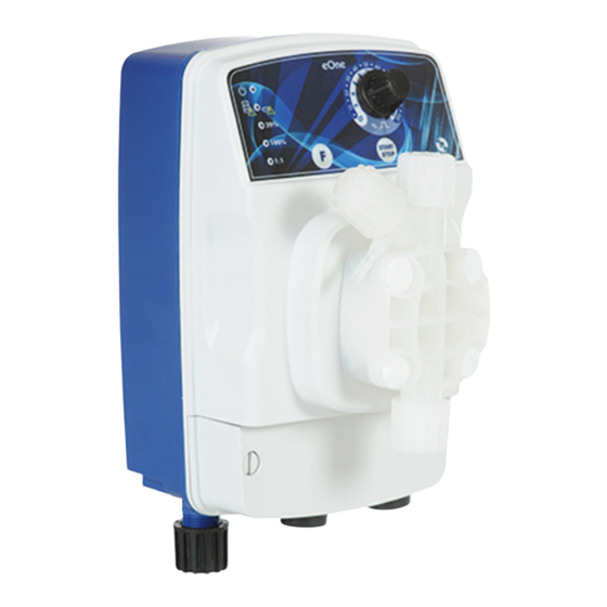
POMPE DOSATRICI ANALOGICHE SERIE EONE MA Principio di funzionamento II funzionamento della pompa dosatrice è assicurato da una membrana in PTFE (teflon®) montata sul pistone di un elettromagnete. Quando il pistone dell’elettromagnete viene attratto, si produce una pressione nel corpo pompa con una espulsione di liquido dalla valvola di mandata. -
Page 8: Dimensioni Di Ingombro
I valori indicati sono da intendersi con una tolleranza del +/- 5% e sono relativi ad una serie di test effettuati su apparecchiature analoghe con acqua alla temperatura di 20°C. Dimensioni di ingombro Fig. 1 - Dimensioni in mm. Placca per il fissaggio a parete. Materiali a contatto con l’additivo Nella configurazione standard le pompe della serie “eOne”... -
Page 9: Collegamento Elettrico
fig.2a). Per liquidi che emanano esalazioni aggressive, non installare la pompa a diretto contatto con i fumi e adottare le necessarie precauzioni per evitare un deterioramento precoce dell’apparecchiatura. Nel caso di installazione sottobattente, ossia con pompa posizionata al di sotto del livello del liquido del serbatoio, (fig. 2b), potrebbe verificarsi il fenomeno del sifonamento. - Page 10 1. Asportare il sigillo sulla ghiera (2) 2. Inserire il tubo attraverso ghiera (2) e la boccola (3) 3. Spingere l’estremità del tubo (1) sul beccuccio conico dell’ugello (4) 4. Accostare l’ugello (4) sul raccordo 5. Serrare la ghiera (2) sul raccordo (5) Fig.4 –...
-
Page 11: S C H Em A D I Imp I Ant O T Ip Ic
Schema di impianto tipico Raccordo di iniezione Valvola di iniezione Valvola di contropressione Manometro Valvola di sfioro Presa per alimentazione elettric Serbatoio additivo Filtro di fondo Sonda di livello Fig. 6 – Impianto tipico Sia sul tubo di mandata che su quello di aspirazione evitare curve eccessive al fine di evitare strozzature sul tubo stesso. -
Page 12: Istruzioni Operative
In questo caso è indispensabile tener presente quanto segue: • sostituire il tubetto PVC trasparente flessibile di aspirazione con un tubetto in polietilene semi rigido di mandata. • togliere preventivamente dal corpo pompa tutta l’acqua presente, infatti se questa si miscela con l’acido solforico genera una forte quantità... -
Page 13: Funzioni Under -Load E O Ve R - L O A
UNDER-LOAD (vedi paragrafo), la pompa dosatrice segnala la situazione e smette di dosare il LED (8) si pone sul rosso fisso. g) OVER-LOAD (vedi paragrafo), la pompa dosatrice segnala la situazione e smette di dosare il LED (8) si pone sul rverde fisso. -
Page 14: Manutenzione Ordinaria
Collegamento della sonda di livello: collegare i cavi i cavi della sonda ai morsetti 3 e 4. Quando l’altezza all’interno del serbatoio del prodotto da dosare scende sotto il livello minimo prestabilito il contatto si chiude e dopo 5 secondi la pompa dosatrice smette di dosare segnalando l’allarme. -
Page 15: Allegato 1 - Disegni Della Pompa
ALLEGATO 1 – DISEGNI DELLA POMPA viti corpo pompa serrare con coppia di serraggio pari a 180 – 200 N*cm con una chiave esagonale da 2,5 mm 1 -MAGNETE 2 -CORPO POMPA 3 -UNITA’ DI COMANDO 4 – SCHEDA CONTATTI ITALIANO... -
Page 16: Allegato 2 - Viste Esplose
SCHEDA MORSETTI L’ingresso W.METER può essere utilizzato con uscita TTL open collector., ad esempio gli strumenti della serie eSELECT. ALLEGATO 2 – VISTE ESPLOSE 1. Coperchio in plastica con scheda 2. Scheda comandi 3. Cassa in plastica 4. Serigrafia 5. Guarnizione manopola 6. - Page 17 1. Ghiera 2. bussola 3. Ugello 4. O-ring 106 5. Corpo filtro 6. Sfera in ceramica 7. O-ring 3030 8. O-ring 3081 9. Sede valvola 10. Cestello filtrante 1. Ghiera 2. Bussola 3. Ugello 4. O-ring 106 5. Raccordo valvola di iniezione 6.
- Page 18 W a r r an t y ............................2 1 ANALOGIC DOSING PUMPS EONE MA SERIES......................22 O p e rat ing p ri n cip l es .
-
Page 19: Safety
SAFETY Warnings Carefully read the warnings listed below as they contain important information regarding safety during installation, use and maintenance. Keep this manual in a safe place for further consultation. This equipment complies with the 2004/108/EEC directive regarding “electromagnetic compatibility” with the 2006/95/CEE “low voltage directive”. -
Page 20: R I Sk
Risks After removing the packaging, check the pump for any damage. If in doubt do not use the pump and contact qualified personnel. All packaging elements (such as plastic bags, polystyrene, etc.) must be kept out of the reach of children as the material is potentially dangerous. -
Page 21: Analogic Dosing Pumps Eone Ma Series
ANALOGIC DOSING PUMPS EONE MA SERIES Operating principles Dosing pump operation is ensured by a PTFE (teflon®) membrane mounted on the piston of an electromagnet. When the piston of the electromagnet is attracted, pressure is produced in the pump head and liquid is ejected from the discharge valve. -
Page 22: O Ve R A Ll D Im En S Io N
The values listed above are intended to be within a tolerance of +/- 5%. They were obtained by a series of test performed on similar equipments with water at temperature of 20°C. Overall dimensions Fig. 1 - Dimensions in mm. Plate for wall mounting. Material in contact with the additive In the standard configuration the pumps of the "eOne"... -
Page 23: E L E Ct Ri C Al Sch Em
Locate the pump as shown in fig.2 taking into account that it can be located over or under the liquid level within a maximum difference of 1,5 meters. The injection point must always be located higher than the liquid to be dose. If the plant being treated operates at atmospheric pressure (free discharge additive) and the additive tank must be placed higher than the injection point (Fig. - Page 24 1. Remove the seal from ring nut (2) 2. Insert tube through ring nut (2) and bush (3) 3. Press the hose end (1) onto the conic adapter of the nozzle (4) 4. Place the nozzle (4) onto the nipple 5.
-
Page 25: T Yp Ic A L In Sta L L At Io
Typical installation Main pipeline Injection valve Backpressure valve Pressure gauge Relief valve Power supply plug Chemical tank Foot filter Level probe Fig. 6 – Typical installation Avoid unnecessary curves and narrow on both the discharge and suction pipes. Apply a 3/8 " or ½" BSP female nipple on the conduct of the plant to be treated, in the most suitable location for the injection of the product to be dosed. -
Page 26: Regulations For Sulphuric Acid Additive (Max. 50%)
REGULATIONS FOR SULPHURIC ACID ADDITIVE (MAX. 50%) In this case it is necessary to take into account the following: • replace the flexible cristal PVC suction hose with semi-rigid polyethylene hose. • Remove all water present in the pump head (if water mixes with sulphuric acid a great amount of gas is generated which will overheat the area and cause damage to the valves and pump head). -
Page 27: U N D Er - L O A D And O V E R- L O A D F U N Ct I O N
UNDER-LOAD (see section), the pump stop dosing and the red LED lights up; OVER-LOAD (see section), the pump stop dosing and the red LED lights up; UNDER-LOAD and OVER-LOAD functions The innovative HRS technology has allowed to create a range of metering pumps capable of detecting pressure changes within the plant or malfunctions associated with these changes. -
Page 28: Ordinary Maintenance
ORDINARY MAINTENANCE An Ordinary and accurate maintenance with a programmed check, guarantee the preservation over time and the proper functioning of the systems. Therefore we recommend that the user follow our advice and maintenance of a service contract and assistance programmed with one of our Technical Support Center. Check at least every 6 months functioning of the pump. -
Page 29: Appendix 1 - Pump Drawings
APPENDIX 1 – PUMP DRAWINGS 1. pump head screws to tighten the four screws use a dynamometer screwdriver set to a tightening torque of 180÷200 Nxcm using a hexagonal insert of 2,5 mm 1 -ELECTROMAGNET 2 –PUMP HEAD 3 –PC BOARD 30 ENGLISH... -
Page 30: Appendix 2 - Exploded Views
SCHEDA MORSETTI APPENDIX 2 – EXPLODED VIEWS 1. Plastic casing 2. Plastic cover 3. Pump head 4. Electromagnet 5. Pump gasket 6. PC-board 7. Knob basket 8. Adjustment knob 9. Flange 10. Diaphragm 11. Pump head basket 12. power cord ENGLISH 31... - Page 31 1. Ring nut 2. Bush 3. Nozze 4. O-ring 106 5. Body filter 6. Ceramic ball 7. O-ring 3030 8. O-ring 3081 9. Valve seat 10. Filterinig basket 1. Ring nut 2. Bush 3. Nozze 4. O-ring 106 5. Injection valve nipple 6.
- Page 32 COD. DMU00190ML1-A (03-2014)
Need help?
Do you have a question about the eOne MA and is the answer not in the manual?
Questions and answers