
Subscribe to Our Youtube Channel
Related Manuals for HURST ML-630-SI


Summary of Contents for HURST ML-630-SI
- Page 1 Built to extend lives.™ Instruction manual for rescue equipment Hydraulic power unit ML-630-SI 375070085 EN Edition 02.2015 replaces 11.2014 (Original instruction manual)
-
Page 3: Table Of Contents
Content Page 1. Danger classi cations 2. Product safety 3. Proper use 4. Power unit designation 5. Functional description 5.1 General information 5.2 Installation of the power unit 5.3 Motor 5.4 Valves 5.5 Pumps 5.6 Frame with side sections 5.7 Connection to the rescue equipment 6. - Page 4 Content Page 13. Technical data 13.1 Power unit 13.2 Noise emissions 13.3 Sparking plug 13.4 Sparking plug spanner 13.5 Fuel 13.6 Engine oil 13.7 Hydraulic fl uid recommendation 13.8 Operating and storage temperature range 14. EC Declaration of Conformity 15. Notes...
-
Page 5: Danger Classi Cations
1. Danger classifi cations We differentiate between various different categories of safety instructions. The table shown below shows you an overview of the assignment of symbols (pictograms) and signal words to the speci c danger and the possible consequences. Damage / Pictogram Key word Defi... -
Page 6: Product Safety
2. Product safety HURST products are developed and manufactured to ensure the best performance and quality when used as intended. The safety of the operator is the most important consideration in product design. Furthermore, the operating instructions are intended to help in using HURST products safely. - Page 7 (additions or conversions) to the device and secure it. Repair the equipment without obtaining the fault immediately. approval of HURST beforehand. Observe all safety and danger All safety and danger information on the device and in information on the device must the operating instructions.
- Page 8 If you spill any fuel when using Refuelling whilst the engine is combustion engines, you running is strictly prohibited! must remove the spilled fuel completely before starting the engine. Keep combustion engines and All damaged electrical their fuels away from sources components e.g.
- Page 9 The generally applicable, legal and other binding national and international regulations pertaining to the prevention of accidents and protection of the environment apply and are to be implemented in addition to the operating instructions. WARNING/CAUTION! The device is intended exclusively for the purpose stated in the operating instructions (see chapter "Proper Use").
-
Page 10: Proper Use
NOTE: Always register your hydraulic unit on the HURST Jaws of Life internet site. This is the only way to guarantee your extended warranty cover. Before you use couplings from a different company, you must contact HURST... -
Page 11: Power Unit Designation
5. Functional description 5.1 General information In the case of all HURST hydraulic power units, the hydraulic pump is operated with a motor. The pump conveys the uid from the hydraulic oil tank and builds up the pressure in the tool. -
Page 12: Installation Of The Power Unit
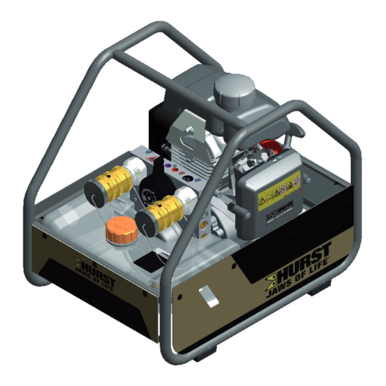
5.2 Installation of the power unit 1 Gasoline tank 2 Hydraulic uid tank 3 Engine with hydraulic pump 4 Connecting block with control valves 5 Speed adjusting lever 6 Carrying handle 7 Cable-pull starter 8 Valve control lever 9 "TURBO" control lever 10 Mono-coupling (female) 11 Fuel tank cap 12 Filler cap hydraulic uid... -
Page 13: Motor
The setting is adjusted by moving the speed adjusting lever. NOTE: The engine installed in the HURST power units does not match every detail of the engine described in the manufacturer's separate operating instructions. Nevertheless, it is important that you follow all safety rules and operating, maintenance and storage instructions in the separate engine instructions as absolute since they are not affected by adjustments made by HURST. -
Page 14: Valves
(blue)) must be connected to the pump block. The rescue equipment is connected to the hose assemblies. Model ML-630 units are equipped with a SIMO connecting block. The connecting block of the ML-630-SI also has a TURBO function. With a switching lever, either both connected devices can be supplied simultaneously with hydraulic uid, or a single device can be supplied with double the volume (= TURBO function). -
Page 15: Pumps
5.7 Connection to the rescue equipment Connection to the rescue equipment is via extension hose pairs or via hose reels. They are supplied in various lengths. (For specifi c details, please consult the HURST range of accessories or contact your HURST dealer.) -
Page 16: Connecting The Hoses / Devices
In cases of doubt, you must consult HURST directly before connecting the equipment! Coupling the mono-couplings The hose lines / units are connected via quick-disconnect coupling halves (female and male) to the hydraulic pump or hose reel in such a way that they cannot be swapped over. - Page 17 Remove the dust caps before coupling together. Then push the male and female parts together and turn the locking sleeve on the female coupling in the direction "1" until the locking sleeve clicks in place. The connection has been made and locked. Decoupling is accomplished by turning the locking sleeve in direction "0".
-
Page 18: Set-Up And Start-Up
The unit is to be set up in a suitable location (secure location / at surface / suf cient distance from vehicles, loads, sources of ignition, etc.). HURST units work perfectly at an angle of up to 20°. However, in order to guarantee maximum safety and uid withdrawal, they should be operated in as horizontal a position as possible. - Page 19 6. Open the venting plug on the pump block, tilt the power unit backwards by approx. 45° (see illustration) and wait until oil comes out from the bolt. Pump block ML-630-SI Venting plug 7. When oil comes out at the venting plug, the air has been removed from the pump. First close the venting plug and then return the power unit to the level.
-
Page 20: Operation
7.2.3 Commissioning (after the fi rst fi lling or prior to use) 1. Check the uid level of the engine oil, the hydraulic uid and the fuel tank. Top up if necessary. For precise reading off of the uid levels and for lling, the hydraulic unit should be as level as possible. -
Page 21: Turning The Engine Off
8.2 Turning the engine off 1. Set the ON / OFF switch to the OFF position. 2. When the engine has come to a standstill, close the fuel tap. For more details on switching off the engine, please refer to the separate operating instructions of the engine manufacturer! CAUTION! Never touch hot engine parts: this could result in severe burns! -
Page 22: Controlling The Valves
(de-pressurised) prior to starting the engine in order to prevent unwanted movements of connected hydraulic equipment. 8.4.1 "Simultaneous operation" control valve (SIMO) ML-630-SI A switching lever that controls the valves (see the top illustration) is located on the pump block. Both mono-... -
Page 23: Dismantling The Equipment / Deactivation Following Operation
9. Dismantling the equipment / deactivation following operation Once the work has been completed, all connected equipment is to be reset to its neutral position (storage position) before the unit is shut down. You can then switch off the engine of the power unit. -
Page 24: Tests
(when necessary also use screens). HURST offers a suitable test kit for the function test of the hydraulic units. (For specifi c details, please consult the HURST range of accessories or contact your HURST dealer.) -
Page 25: Visual And Function Check
• Check for leaks. Functional test • Unconventional or noticeable noises heard during operation • Cable-pull starter fully functional, • Engine switch fully functional, • Test for maximum load. NOTE: use the HURST test kit, including testing instructions, for the function test. -
Page 26: Maintenance And Repair
11. Maintenance and repair 11.1 General information HURST hydraulic units model ML-630 require only limited maintenance. For service work, special training is unnecessary; however, knowledge of the function of the power unit, the legal safety instructions and dealing with the required tools are basic prerequisites. -
Page 27: Service Work On The Hydraulic Unit
Any other components in the unit may only be replaced if: - You have participated in an appropriate HURST service training course. - You have the express permission of HURST customer service (upon request, we will check for the grant of permission. Examination in each individual case... - Page 28 1. Remove damaged and/or illegible decals. 2. Clean surfaces with industrial alcohol. 3. Af x new decals. Take care to af x the decals in the correct positions. If this is no longer known, you should ask your authorised HURST dealer or contact HURST directly.
-
Page 29: Additional Service Work
You must conduct the following service measures every 200 operating hours: • Replace the sparking plug • Replace air lter (The following service work should be executed by an authorised dealer, HURST directly or the engine manufacturer.) You must conduct the following service measures every 300 operating hours: •... - Page 30 11.3.1 Replacing and cleaning the air fi lter NOTE: Keeping the air lter in good condition is extremely important. Penetrating dirt leads to damage and wear in the engine in case of incorrect installation, incorrect damage or unsuitable lter inserts. Always keep the air lter insert clean.
- Page 31 11.3.2 Replacing, cleaning and setting the sparking plug Procedure: In order to deliver good performance, the sparking plug must have a correct electrode gap and be free from deposits. 1. Detach the sparking plug connector and remove any dirt near the sparking plug. 2.
- Page 32 - hydraulic uid continues to leak in the coupled/uncoupled state. WARNING/CAUTION! Never repair couplings: they must be replaced by genuine HURST parts! Procedure for coupling to valve block: 1. First empty the hydraulic tank as described in the chapter "Replacing the hydraulic uid".
- Page 33 - hydraulic uid continues to leak in the coupled/uncoupled state. WARNING/CAUTION! Never repair couplings: they must be replaced by genuine HURST parts! During assembly tighten the union nuts on the hose line to a torque of M = 35 Nm.
-
Page 34: Fault Analysis
Fault in the fuel line Shut down immediately and have repaired by authorised dealer, motor NOTE: / engine manufacturer In case of faults or directly by HURST which directly affect Inspect engine Cable-pull starter Activate cable-pull the combustion switch starter... - Page 35 Defective pump unit Have repaired by valve. hydraulic unit authorised dealer or directly by HURST Connect a The previously Recti cation see different unit and connected unit is operating instructions check whether defective.
- Page 36 HURST Pump block defective Have repaired by authorised dealer or directly by HURST Connected unit Recti cation see defective operating instructions of the connected unit During function test: Check the details...
- Page 37 Leaking uid Radial shaft seal on the Have repaired by between engine and drive shaft is defective authorised dealer or ange bearing directly by HURST Hydraulic uid milky Water / condensation in Replace the hydraulic and cloudy the system uid immediately Hoses cannot be Pressure too high (e.g.
- Page 38 In case of faults which affect the combustion engine, please also observe the instructions in the separate operating instructions of the engine manufacturer. Contact an authorised HURST dealer or the HURST Customer Service Department directly if the malfunctions cannot be recti ed.
-
Page 39: Technical Data
The following tables contain only the technical data required for standard acceptance. Additional data concerning your unit can be obtained from HURST on request. The limitation of the max. ll quantity of the hydraulic tank results from the "operability at an incline" prescribed in the standards. - Page 40 13.1.2 Technical data ML-630-SI Device type ML-630-SI Article number 375070000 Motor type 4-stroke gasoline engine [kW] Engine power rating [HP] [min Engine speed 3000 / 3800 [rpm.] [l/min] 2 x 1.0 / 2 x 1.2 Feed rate simultaneous (HD) [gal.-US/min] 2 x 0.27 / 2 x 0.32...
-
Page 41: Noise Emissions
Explanation of dual number noise emission values according to DIN EN 13204:2012-09 Serial number of the machine, operating conditions and other characteristic properties: Model ...ML-630-SI, type ...375070000, maximum working pressure ...500 bar, engine speed ..3800 [1/min] / [rpm] INDICATED DUAL NUMBER NOISE EMISSION VALUES according to EN ISO 4871 Measured A-rated emission sound pressure level LpA, in dB, referred to 20 Pa ..88... -
Page 42: Sparking Plug
13.3 Sparking plug Sparking plug type: CR5HSB (NGK) U16FSR-UB (DENSO) 13.4 Sparking plug spanner Universal joint sparking plug spanner with spanner size 16 mm (5/8 inch) 13.5 Fuel Fuel: Lead-free gasoline ROZ 91 to ROZ 98... -
Page 43: Engine Oil
13.6 Engine oil 13.7 Hydraulic fl uid recommendation Mineral oil DIN ISO 6743-4 for HURST hydraulic equipment and others Oil temperature range Oil designation Viscosity rating Remarks -20 ..+55°C HM 10 VG 10 Oil temperature range Oil designation Viscosity rating Remarks -4.0 .. -
Page 44: Ec Declaration Of Conformity
14. EC Declaration of Conformity... -
Page 45: Notes
15. Notes... - Page 48 Before connecting the equipment, make sure that all the components used are suitable for the maximum operating pressure of the hydraulic unit! In cases of doubt, you must consult HURST directly before connecting the equipment! Please dispose of all packaging materials and removed items properly.
Need help?
Do you have a question about the ML-630-SI and is the answer not in the manual?
Questions and answers