
Related Manuals for HURST P 650


Summary of Contents for HURST P 650
- Page 1 Built to extend lives.™ Instruction manual for rescue equipment Hydraulic power units P 650 275710085 EN Edition 11.2014 replaces 01.2014 (Original instruction manual)
-
Page 3: Table Of Contents
Contents Page 1. Hazard classes 2. Product safety 3. Intended use 4. Labelling of the units 5. Functional description 5.1 General information 5.2 Structure of the units 5.3 Motor variants 5.4 Valve variants 5.5 Pumps 5.6 Frame with side parts 5.7 Connection to the rescue equipment 5.8 Hose reels 5.9 Carrying handle... - Page 4 Contents Page 11. Maintenance and repair 11.1 General information 11.2 Maintenance work on the hydraulic unit 11.3 Additional maintenance work on units with a combustion engine 11.4 Maintenance work on mounted hose reel 12. Troubleshooting 13. Technical data 13.1 Unit 13.2 Noise emissions 13.3 Sparking plug 13.4 Sparking plug socket...
-
Page 5: Hazard Classes
1. Hazard classes We distinguish between various categories of safety instructions. The table below gives you an overview of the assignment of symbols (pictograms) and key words to the speci c hazard and possible consequences. Damage / Pictogram Key word Defi... -
Page 6: Product Safety
The safety of the operator is the most important consideration in the product design. Moreover, the operating instructions are intended to help the safe use of HURST products. The generally applicable legal and other binding regulations pertaining to the prevention of accidents and protection of the environment apply and are to be complied with in addition to the operating instructions. - Page 7 / the operation of the device. inspections of the equipment. When working in the proximity Only genuine HURST of live components and accessories and spare parts wires, appropriate steps must are to be used for repairs.
- Page 8 Keep combustion engines and All damaged electrical their fuel away from ignition components e.g. scorched sources, as otherwise there is cables, etc. are to be replaced the danger of an explosion. immediately! To avoid the danger of re Damage to electrical when using combustion components may only be engines, ensure suf cient...
- Page 9 WAR N I N G / C A U TION / ATT ENTION ! The device is to be used exclusively for the purpose stated in the operating instructions (see chapter "Intended Use"). Any form of use beyond this is not considered intended use.
-
Page 10: Intended Use
Two of these cylinders should never be coupled and operated simultaneously! NOTE: Always register your hydraulic unit on the HURST website. This is the only way to guarantee your extended warranty cover. You must always contact HURST or an authorized dealer before using couplings from another manufacturer. -
Page 11: Labelling Of The Units
5. Functional description 5.1 General information The hydraulic pump on all HURST hydraulic units is always operated by a combustion engine or electric motor. The pump conveys uid from the reservoir and builds up hydraulic pressure. The distribution of the uid is controlled by mounted valves. -
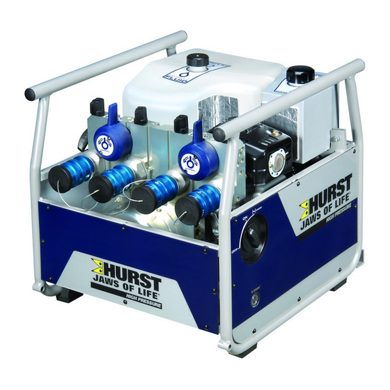
Page 12: Structure Of The Units
5.2 Structure of the units 1 Hydraulic uid reservoir 2 Gasoline tank 3 Engine with hydraulic pump 4 Connecting block with control valves 5 Engine switch 6 Electric starter button 7 Pull cord starter 8 Valve control lever 9 "TURBO" control lever 10 Mono-couplings 11 Hydraulic uid ll cap 12 Gasoline ll cap... -
Page 13: Motor Variants
If the battery is still not charged after the unit consumes a full tank of fuel, the causes may include the following: - the contacts (connector) have come loose and must be connected again. - the battery is defective and must be replaced. - the generator or engine is damaged. In this case, contact HURST customer service directly. -
Page 14: Valve Variants
5.4 Valve variants The valves are always permanently installed in a connecting block. This block is integrated directly in the hydraulic unit. Both hose lines (pressure and return) are always connected to the connecting block. The units are tted either with a SIMO or a 4POWER connecting block. Both connecting blocks also have a TURBO function. -
Page 15: Pumps
5.5 Pumps HURST hydraulic units are equipped with a double- ow or four- ow pump depending on the type. The pumps are permanently connected to the connecting block. Double- ow pump for operation with SIMO valve Four- ow pump for operation with 4POWER valve The pumps used are always equipped with two pressure levels for each pump capacity, one low-pressure and one high-pressure level. -
Page 16: Hose Reels
The toolholder is usually designed to attach a SP310 spreader and a type S5xx cutter. Needless to say, it is possible to adapt the mount to accommodate all HURST cutters and spreaders as well as modify it at a later date. -
Page 17: Connection Of The Hose Lines / Devices
Before connecting equipment, make sure that all the components used are suitable for the maximum operating pressure of the hydraulic unit! In cases of doubt, you must consult HURST directly before connecting the equipment! The hose lines / devices are connected to the hydraulic pump or hose reel via mono-coupling halves (male and female) without any risk of confusion. - Page 18 Before coupling, remove the dust protection caps, then connect male and female couplings and turn the locking sleeve of the female coupling in direction "1" until the locking sleeve latches. The connection has now been made and locked. Decoupling is accomplished by turning the locking sleeve in direction "0".
-
Page 19: Set-Up And Start-Up
The unit is to be set up in a suitable location (safe location / at surface / suf cient distance from vehicles, loads, sources of ignition, etc.). HURST units work perfectly at an angle of up to 20°. However, in order to guarantee maximum safety and uid withdrawal, they should be operated in as level a position as possible. -
Page 20: Operation
This procedure means that the pump can slowly draw uid in and be well vented. The hydraulic uid reservoir is equipped with automatic venting, which means no further venting measures are required. 4. Check the uid levels in the reservoirs again. If necessary, top off the uid. 5. -
Page 21: Stopping The Motor/Engine
8.1.2 Electric motors Before starting the electric motors, check that all electrical connections and cables are in proper order. First of all, connect the power cable (for motors with power supply) to the supply socket. The motor is started by pressing the ON/OFF switch on the side of the unit. The ring around the switch lights up when the unit is switched on. -
Page 22: Refuelling (Combustion Engines Only)
8.3 Refuelling (combustion engines only) The engine must be switched off during refuelling! Procedure: 1. Open the ll cap on the fuel tank. 2. Fill the tank with fuel up to the maximum mark. WARNING / CAUTION / ATTENTION! Make sure you do not spill any fuel! If fuel comes into contact with hot engine components, in particular, there is a risk it may ignite and start a re! If fuel is spilled by accident, it must be cleaned up immediately using a suitable absorbent cloth. - Page 23 NOTE: All shift levers must always be moved all the way to their end position. 8.4.2 "4POWER mode" control valve Six levers are located on the connecting block of this valve. Each of the four small levers is assigned to a pressure port. Actuating the respective lever regulates the pressure in the corresponding pressure hose ("...
-
Page 24: Hose Reels
8.5 Hose reels 8.5.1 Locking brake The locking brake is designed to prevent extension hose pairs from unrolling during transportation! Pull and turn knob "A" through 90° to release the locking brake. To apply the locking brake, turn knob "A" through approx. 90° until it engages automatically. 90°... - Page 25 8.5.4 Rolling up NOTE: We recommend using the crank handle to roll up the hoses! - Fold out the crank handle. - Check that the locking brake on the double hose reels is released. - Align the reels so that the unrolled hoses are rolled up in a straight line. You will nd that the hoses roll up more easily.
-
Page 26: Telescopic Carrying Handles
8.6 Telescopic carrying handles The hydraulic units could be retro tted with handles if required. The handles should be used to transport the P650. The telescopic carrying handles are screwed directly to the frame. The blanking plugs must be removed before the handles can be attached. Turn the handles clockwise (approx. -
Page 27: Toolholder
8.7 Toolholder A device must rst be detached from retaining clip "D" before it can be removed from the toolholder. The device is then easy to remove. The device is tted in the reverse order. Make sure that the handle tube on the rescue equipment engages properly in the retaining clip. - Page 28 Procedure (fi tting and adjusting the toolholder): NOTE: If you wish to install a toolholder at a later time or adapt an existing mount to a new device, follow the working steps described below. 1. Mount the retaining clip "A" on block "C" and secure using the screws "B".
- Page 29 3. Then mount bracket "H" for the spreader and combi tool as well as bracket "J" for the cutters to mounting plate "K" (see illustration below). The brackets are secured in position using screws "L", "M", "N" and "O" as well as washers "P" and nuts "Q". One exception is the retainer for type S700 cutters.
- Page 30 4. Mounting plates "G" and "K" are secured to the frame of the unit using screws "T" as shown in the illustration below.
- Page 31 5. Now adapt the brackets to the respective devices. Loosen the xing screws "F" and "S" or nuts "Q" slightly so that the brackets are easy to move. Do not unscrew the screws or nuts completely. The elongated holes "U" in the mounting plates allow you to adapt the brackets to almost every device or individual position of your choice.
-
Page 32: Removing The Device / Deactivation Following Operation
9. Removing the device / deactivation following operation Once work has been completed, all connected equipment is to be reset to its base position before the unit is shut down. You can now stop or switch off the motor/engine on the unit and disconnect it from the mains supply, if using an electric motor. -
Page 33: Tests
(use protective shields if required). HURST offers a suitable test kit for the functional check of the hydraulic units. (For specifi c details, please consult the HURST range of accessories or contact your HURST dealer). -
Page 34: Hydraulic Units With Combustion Engine
Should either of the above occur several times within a month or the maximum pressure is not reached during the functional check, contact HURST customer service immediately. See the chapter "Troubleshooting" for contact details. -
Page 35: Hydraulic Units With Electric Motor
• No suspicious noises • Starter fully functional • Engine switch fully functional • Test for maximum load (Recommendation: use the HURST test kit, including testing instructions, for the functional check). 10.3 Hydraulic units with electric motor Visual inspection Hydraulic units •... -
Page 36: Hose Reels
11. Maintenance and repair 11.1 General information HURST type P 650 hydraulic units have an extremely complex design but require minimal maintenance work. Maintenance work does not require special training, but knowledge on operating the unit, statutory safety regulations and handling all the necessary tools are basic requirements. -
Page 37: Maintenance Work On The Hydraulic Unit
Further components in the unit may only be replaced if: - you have taken part in appropriate HURST service training, - you have the express permission of HURST Customer Service (after request, veri cation that permission may be granted. Veri cation required in each... - Page 38 1. Remove damaged and/or illegible labels. 2. Clean surfaces with industrial alcohol. 3. Af x new signs. Ensure that you attach the signs in the correct position. If this is no longer known, you should ask your authorized HURST dealer or contact HURST directly.
-
Page 39: Additional Maintenance Work On Units With A Combustion Engine
11.3 Additional maintenance work on units with a combustion engine (also read the separate instructions provided by the engine/motor manufacturer) Perform the following maintenance work every 50 operating hours: • Wash the air lter element. Wash more frequently when using the unit in a dirty or dusty environment. - Page 40 11.3.1 Changing and cleaning the air fi lter Maintaining the air lter in good condition is essential. The ingress of dirt due to incorrect installation, incorrect maintenance or unsuitable lter inserts causes damage and excess wear to the engine/motor. Always keep the air lter insert clean.
- Page 41 11.3.2 Changing, cleaning and adjusting the sparking plug Procedure: 1. Remove the right side panel on the hydraulic unit by detaching the mounting clips. 2. Remove the sparking plug connector. The connector is attached rmly and may require greater effort to remove. During removal, make sure you do not bend the connector or exert lateral force on the sparking plug.
- Page 42 11.3.4 Externally charging and replacing the starter battery Procedure: 1. Remove the left side panel "A" on the hydraulic unit by detaching the mounting clips "B". 2. Starter battery "C" is now visible. First disconnect the negative ("-") and then the positive terminal ("+") on the battery.
-
Page 43: Maintenance Work On Mounted Hose Reel
11.4 Maintenance work on mounted hose reel A visual inspection of the tted hoses and couplings is to be carried out after every use or every six months. Components showing obvious signs of damage or leaks must be replaced. If screwed connections start to leak, check whether they are tight rst of all. If the leak continues after the screwed connection has been tightened, the screwed connection is defective and must be replaced. - Page 44 - hydraulic uid continues to leak in a coupled/uncoupled state. WARNING / CAUTION / ATTENTION! Never repair couplings: they must be replaced with genuine HURST parts! Procedure for couplings on the valve block: 1. First of all, empty the hydraulic reservoir as described in the chapter "Replacing the hydraulic uid".
- Page 45 Procedure for couplings on hose pairs: 1. First of all, empty the hydraulic reservoir as described in the chapter "Replacing the hydraulic uid". 2. Pull the cover back from the couplings. 3. Loosen the union nuts on the hose lines and remove the coupling. CAUTION! As the case may be, make sure that port 'T' / 'T1' of the hose reel is always connected to port 'T' of the mono-coupling.
-
Page 46: Troubleshooting
/ engine manufacturer or directly by HURST Extension cable Cable not completely Uncoil the power cable or cable drum uncoiled completely used? Cable losses in... - Page 47 Check fuel line Fault in the fuel line Shut down immediately and have repaired by authorized dealer, motor / engine manufacturer or directly by HURST Check the starter Starter button or pull Actuate starter button or button and cord starter not...
- Page 48 Defective pump unit Have repaired by authorized dealer or directly by HURST Connect another The previously For the solution, device and connected device is consult the operating check whether it defective.
- Page 49 HURST Defective pump block Have repaired by authorized dealer or directly by HURST Connected device is For the solution, defective consult the operating instructions for the connected device During the...
- Page 50 Radial shaft seal Have repaired by between engine on the drive shaft is authorized dealer or and ange bearing defective directly by HURST Hydraulic uid Water / condensation Immediately replace milky and cloudy in the system hydraulic uid Hose line cannot Pressure too high (e.g.
- Page 51 Defective shaft Repair of fault by piece and shaft authorized dealer, leaking? specially trained HURST staff or directly by HURST Hydraulic uid Connection Hose lines defective. Replace hoses escaping from hoses damaged? the connections...
- Page 52 If it isn’t possible to rectify the malfunctions, inform an authorized HURST dealer or the HURST customer service department immediately! The address for the HURST customer service department is: HURST JAWS OF LIFE, INC A Unit of IDEX Corporation 711 N. Post Road...
-
Page 53: Technical Data
The following tables contain only the technical data required for standard acceptance. Additional data concerning your unit can be obtained from HURST on request. The restriction for the maximum ll quantity of the hydraulic reservoir is calculated from the "operability in inclined position" speci cations in the relevant standards. - Page 54 13.1.2 Type series P 650 SE and P 650 SE - DHR P 650 SE P 650 SE - DHR Device type 275750000 275752000 Ref. number 230V / 60 Hz ; Electric motor Motor type [kW] 2.65 Power [HP] 3.55...
- Page 55 13.1.3 Type series P 650 SG P 650 SG P 650 SG - ES Device type 275710000 275720000 Ref. number 4-stroke gasoline engine Motor type [kW] Power [HP] 5.63 [min 3300 Speed [rpm.] [MPa] Max. operating pressure [psi.] 10000 (HP) [MPa] Max.
- Page 56 13.1.4 Type series P 650 SG - DHR P 650 SG - DHR P 650 SG - ES - DHR Device type 275712000 275722000 Ref. number 4-stroke gasoline engine Motor type [kW] Power [HP] 5.63 [min 3300 Speed [rpm.] [MPa] Max.
- Page 57 13.1.5 Type series P 650 4E P 650 4E Device type 275780000 Ref. number 240V / 60 Hz ; Electric motor Motor type [kW] Power [HP] 5.36 [min 3540 Speed [rpm.] [MPa] Max. operating pressure (HP) [psi.] 10000 [MPa] Max. operating pressure (LP) [psi.]...
- Page 58 13.1.5 Type series P 650 4G P 650 4G P 650 4G - ES Device type 275730000 275740000 Ref. number 4-stroke gasoline engine Motor type [kW] Power [HP] 6.84 [min 3600 Speed [rpm.] [MPa] Max. operating pressure [psi.] 10000 (HP) [MPa] Max.
- Page 59 13.1.6 Type series P 650 4G - DHR P 650 4G - DHR P 650 4G - ES - DHR Device type 275732000 275742000 Ref. number 4-stroke gasoline engine Motor type [kW] Power [HP] 6.84 [min 3600 Speed [rpm.] [MPa] Max.
-
Page 60: Noise Emissions
P 650 S E P 650 S G P 650 4 G P 650 4 E Device type P 650 S E - P 650 S G - P 650 4 G - No-load operation [dB(A)] (measuring distance 1 m) -
Page 61: Engine Oil
13.6 Engine oil 13.7 Hydraulic fl uid recommendation Mineral oil DIN ISO 6743-4 for HURST 10K hydraulic equipment and others Oil temperature range Oil code Viscosity rating Remarks -20 ..+55°C HM 10 VG 10 Oil temperature range Oil code... -
Page 62: Epa Warranty
EMISSIONS COMPONENT DEFECT WARRANTY COVERAGE - This emission warranty is applicable in all States, except the State of California. Hurst Jaws of Life at 711 North Post Rd. Shelby, NC. 28150, warrant(s) to the initial retail purchaser and each subsequent owner, that this Nonroad engine (herein “engine”) has been designed, built, and equipped to conform at the time of initial sale to all applicable regulations of the U.S. - Page 63 * Hurst Jaws of Life will either pay for the shipping costs of replacement parts to and from an authorized service center. * Or Hurst Jaws of Life will provide for a service technician to come to the owner to make the warranty repair.
- Page 64 All repairs qualifying under this limited warranty must be performed by a service dealer au- thorized by Hurst Jaws of Life. In the event that any emission-related part is found to be defective during the warranty period, you shall notify Hurst Jaws of Life customer service department at (800.537.2659)
-
Page 65: Declaration Of Conformity
15. Notes... - Page 68 Before connecting equipment, make sure that all the components used are suitable for the maximum operating pressure of the hydraulic unit! In cases of doubt, you must consult HURST directly before connecting the equipment! Please dispose of all packaging materials and dismantled parts properly.
Need help?
Do you have a question about the P 650 and is the answer not in the manual?
Questions and answers