
Related Manuals for HURST P 630 SG


Summary of Contents for HURST P 630 SG
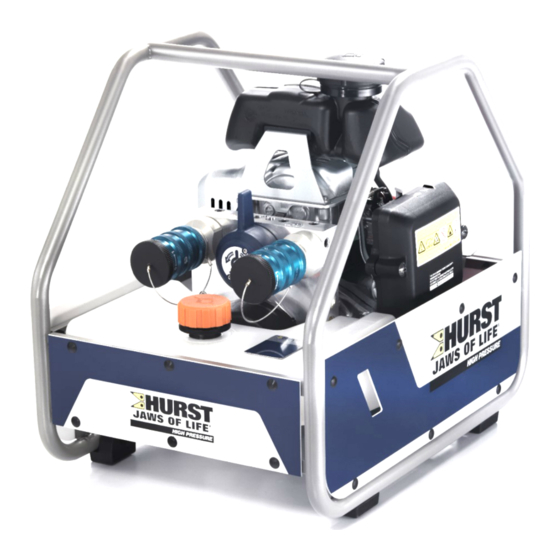
- Page 1 Built to extend lives.™ Instruction manual for rescue equipment Hydraulic power unit P 630 SG 275070085 EN Edition 05.2021 replaces 07.2020 (Original instruction manual)
-
Page 2: Table Of Contents
Content Page 1. Danger classifications 2. Product safety 3. Intended use 4. Power unit designation 5. Functional description 5.1 General information 5.2 Installation of the power unit 5.3 Motor 5.4 Valves 5.5 Pumps 5.6 Frame with side sections 5.7 Connection to the rescue equipment 6. Connecting the hoses / devices 6.1 Coupling the mono-couplings 7. Set-up and commissioning 7.1 Set-up... - Page 3 Content Page 12. Fault analysis 13. Technical data 13.1 Power Unit 13.2 Noise emissions (sound pressure level) 13.3 Sparking plug 13.4 Sparking plug spanner 13.5 Fuel 13.6 Engine oil 13.7 Hydraulic fluid recommendation 13.8 Operating and storage temperature range 14. Notes...
-
Page 4: Danger Classifications
1. Danger classifications We differentiate between various different categories of safety instructions. The table shown below shows you an overview of the assignment of symbols (pictograms) and signal words to the specific danger and the possible consequences. Damage / Pictogram Key word Definition Consequences injury to Death or severe DANGER! Immediate danger injury Potentially Potential death or WARNING! dangerous serious injury situation Less dangerous Minor or slight CAUTION! situation injury Damage to the equipment, Danger of damage damage to the ATTENTION! to property/ environment, environment damage to surroundings Handling tips and No injury/damage other important/... -
Page 5: Product Safety
2. Product safety HURST products are developed and manufactured to ensure the best performance and quality when used as intended. The safety of the operator is the most important consideration in product design. Furthermore, the operating instructions are intended to help in using HURST products safely. The generally applicable legal and other binding regulations pertaining to the prevention of accidents and protection of the environment apply and are to be complied with in addition to the operating instructions. The equipment must only be operated by persons with appropriate training in the safety aspects of such equipment – otherwise, there is a danger of injury. We would like to point out to all users that they should read carefully the operating instructions and the instructions contained therein before they use the equipment, and that they should carefully follow such. We further recommend you have a qualified trainer show you how to use the product. - Page 6 In the event of malfunctions, Do not carry out any changes immediately deactivate the (additions or conversions) to the device and secure it. Repair the equipment without obtaining the fault immediately. approval of HURST beforehand. Observe all safety and danger All safety and danger information on the device and in information on the device must the operating instructions. always be complete and in a legible condition. Please ensure that all safety Any mode of operation which covers are present on the compromises the safety and/ equipment and that they are in or stability of the device is proper and adequate condition. forbidden! Safety devices must never be The maximum operating disabled! pressure set on the equipment must not be changed! Make sure before switching Observe all intervals for on/starting up the device and recurring tests and/or during its operation, that this will inspections that are prescribed put no one in danger. or stated in the operating instructions. When working close to live Only original HURST components and cables,...
- Page 7 If you spill any fuel when using Refuelling whilst the engine is combustion engines, you running is strictly prohibited! must remove the spilled fuel completely before starting the engine. Keep combustion engines and All damaged electrical their fuels away from sources components e.g. scorched of ignition since otherwise there cables, etc. are to be replaced will be a danger of explosion. immediately! In order to prevent the danger Damage to electrical of fire, you should ensure components must only adequate ventilation when be repaired by a qualified operating combustion engines electrician in compliance with and you must keep a safety all applicable national and distance of at least 1m (39.4 in.) international safety guidelines to walls and other screens. and regulations. Make sure that the combustion When setting up the units, you engines are always standing on must make sure that they are as flat and horizontal a surface not impaired by the influences as possible to prevent fuel from of extreme temperatures. leaking out. The equipment is filled with When working with or storing hydraulic fluid. This hydraulic the equipment, ensure that the...
- Page 8 The generally applicable, legal and other binding national and international regulations pertaining to the prevention of accidents and protection of the environment apply and are to be implemented in addition to the operating instructions. WARNING/CAUTION! The device is intended exclusively for the purpose stated in the operating instructions (see chapter "Proper Use"). Any other use is not in accordance with its designated use. The manufacturer/supplier is not liable for any damages resulting from improper use. The user bears sole responsibility for such use. Proper use includes observance of the operating instructions and compliance with the inspection and maintenance conditions.
-
Page 9: Intended Use
3. Intended use HURST hydraulic units are specially designed to supply HURST rescue equipment with hydraulic fluid so that this equipment can be used to rescue victims of road, rail or air traffic accidents as well as from buildings. Their use for supplying pressure / fluid to rescue equipment of other manufacturers is possible, yet requires the technical inspection and approval by HURST in each individual case. CAUTION! The P 630 power units were not developed for being operated without hoses or devices (operating time < 15 minutes). WARNING/CAUTION! The safety instructions in this operating instruction manual concerning the site of erection and type of erection must always be observed! HURST P 630 units are not explosion protected! -
Page 10: Power Unit Designation
4. Power unit designation Type group Motor variants Coding for hydraulic Valve variants power units Valve variants: Simultaneous operation Motor variants: Gasoline engine 5. Functional description 5.1 General information In the case of all HURST hydraulic power units, the hydraulic pump is operated with a motor. The pump conveys the fluid from the hydraulic oil tank and builds up the pressure in the tool. Fluid is distributed to the connected equipment through control valves. The P 630 SG is a power unit with frame and with a gasoline engine and simultaneous operation. -
Page 11: Installation Of The Power Unit
5.2 Installation of the power unit 1 Gasoline tank 2 Hydraulic fluid tank 3 Engine with hydraulic pump 4 Connecting block with control valves 5 Speed adjusting lever 7 Cable-pull starter 9 "TURBO" control lever 10 Mono-coupling (female) 11 Fuel tank cap 12 Filler cap hydraulic fluid 13 Frame 14 Rubber buffer 15 Side panel 16 Air filter 17 Choke 18 Fuel tap 19 ON/OFF switch (engine switch) 22 Engine oil filler cap/dipstick Equipment back... -
Page 12: Motor
Switch position 1 (standard): Speed 3000 1/min " " and Switch position 2: Speed 3800 1/min " ". The setting is adjusted by moving the speed adjusting lever. NOTE: The engine installed in the HURST power units does not match every detail of the engine described in the manufacturer's separate operating instructions. Nevertheless, it is important that you follow all safety rules and operating, maintenance and storage instructions in the separate engine instructions as absolute since they are not affected by adjustments made by HURST. -
Page 13: Valves
5.4 Valves Both valves of the power unit in the pump block are fixed in place. The pump block is fully integrated into the hydraulic power unit. The hose assemblies (pressure line (grey) and return (blue)) must be connected to the pump block. The rescue equipment is connected to the hose assemblies. Model P 630 units are equipped with a SIMO connecting block. The connecting block of the P 630 SG also has a TURBO function. With a “TURBO” control lever, either both connected devices can be supplied simultaneously with hydraulic fluid, or a single device can be supplied with double the volume (= TURBO function). By supplying at double the feed rate, the speed of the connected device is increased. The hoses are connected with the connecting block via mono-couplings. Control valve "simultaneous operation" (SIMO) This valve enables the connection of two pressure hoses and two return hoses. It has two switching options, each of which controls the pressure application of the pressure hose that is marked accordingly. This means that two devices can be supplied with pressure... -
Page 14: Pumps
5.5 Pumps The HURST hydraulic power units model P 630 are equipped with a SIMO connecting block. The pump is rigidly connected to the connecting block. Double-flow pump for operating with SIMO valve The pump used always has two pressure stages per pump feed flow, one low pressure and one high pressure. Low-pressure level (LP) = up to 14 MPa* High-pressure level (HP) = up to 70 MPa* *) 1 MPa = 10 bar) The changeover from low pressure to high pressure is carried out automatically by the pump. This system is secured with a pressure limiting valve. Therefore, the maximum permissible system pressure cannot be exceeded. WARNING/CAUTION! For safety reasons, the pressure set on this valve must not be adjusted (without the approval of HURST directly)! 5.6 Frame with side sections The P 630 hydraulic power unit is mounted within a frame. The frame and side panels are also used, despite the robust design, to protect the power unit from external influences, such as for example, dirt or damage. 5.7 Connection to the rescue equipment Connection to the rescue equipment is via extension hose pairs or via hose reels. They are supplied in various lengths. (For specific details, please consult the HURST range of accessories or contact your HURST dealer.) -
Page 15: Connecting The Hoses / Devices
WARNING/CAUTION! Before connecting the equipment, make sure that all the components used are suitable for the maximum operating pressure of the hydraulic unit! In cases of doubt, you must consult HURST directly before connecting the equipment! 6.1 Coupling the mono-couplings The hose lines / units are connected via quick-disconnect coupling halves (female and male) to the hydraulic pump or hose reel in such a way that they cannot be swapped over. Dust protection caps... - Page 16 Remove the dust caps before coupling together. Then push the male and female parts together and turn the locking sleeve on the female coupling in the direction "1" until the locking sleeve clicks in place. The connection has been made and locked. Decoupling is accomplished by turning the locking sleeve in direction "0".
-
Page 17: Set-Up And Commissioning
7. Set-up and commissioning 7.1 Set-up WARNING/CAUTION! Because of possible spark formation, combustion engine units and electrical equipment cannot be used in an explosion-risk area. Units with combustion engines must not be used in enclosed spaces, as there is a danger of poisoning and/or asphyxiation! The unit is to be set up in a suitable location (secure location / flat surface / sufficient distance from vehicles, loads, sources of ignition, etc.). HURST units work perfectly at an angle of up to 20°. However, in order to guarantee maximum safety and fluid withdrawal, they should be operated in as horizontal a position as possible. 7.2 Commissioning NOTE: The engine oil level must be inspected before the first commissioning or after longer periods of storage. First fill the engine or top up the engine oil! For safety reasons, HURST power units do not contain engine oil upon delivery! ATTENTION! Never mix up the fuel and hydraulic fluid tanks when filling the tank; this can damage the power unit! 7.2.1... - Page 18 4. Now bleed the hydraulic power unit: 5. Open and remove the tank cap so that air enters the tank. 6. Open the venting plug on the pump block, tilt the power unit backwards by approx. 45° (see illustration) and wait until oil comes out from the bolt. Pump block P 630 SG Venting plug 7. When oil comes out at the venting plug, the air has been removed from the pump. First close the venting plug and then return the power unit to the level. 8. Check the fluid levels. Top up if necessary. 9. Now connect the extension hoses and/or hose reels (unless already connected to the unit) and/or couple the rescue equipment.
-
Page 19: Operation
7.2.3 Commissioning (after the first filling or prior to use) 1. Check the fluid level of the engine oil, the hydraulic fluid and the fuel tank. Top up if necessary. For precise reading off of the fluid levels and for filling, the hydraulic unit should be as level as possible. 2. Now connect the extension hoses and/or hose reels (unless already connected to the unit) and/or couple the rescue equipment. 8. Operation 8.1 Starting the engine Before starting the combustion engine, check that the fuel tank is full and that the engine oil level is within the permitted tolerances. If necessary, top up the relevant fluid. -
Page 20: Turning The Engine Off
8.2 Turning the engine off 1. Set the ON / OFF switch to the OFF position. 2. When the engine has come to a standstill, close the fuel tap. For more details on switching off the engine, please refer to the separate operating instructions of the engine manufacturer! CAUTION! Never touch hot engine parts: this could result in severe burns! 8.3 Refuelling The engine must be switched off for refuelling! Procedure: 1. Open the fuel tank cap. 2. Fill the tank with fuel until the fill level is just below the filler opening. WARNING/CAUTION! Be sure not to spill fuel. In particular, hot engine parts must not come into contact with fuel; danger of fire otherwise! If fuel is spilled, it must be cleaned up immediately with a suitable absorbent... -
Page 21: Controlling The Valves
8.4 Controlling the valves 8.4.1 "Simultaneous operation" control valve (SIMO) P 630 SG The pump block also has a “TURBO” control lever, allowing the user to switch to the “TURBO” function (see diagram above). With this function, the switch position of the “TURBO” control lever can be used to supply one of the two connections with double the volume. The "TURBO" function is activated by turning the “TURBO” control lever towards the connection that is to be pressurised at the doubled pumping output. NOTE: The “TURBO” control lever must always be moved completely up to the stop. -
Page 22: Dismantling The Equipment / Deactivation Following Operation
9. Dismantling the equipment / deactivation following operation Once the work has been completed, all connected equipment is to be reset to its neutral position (storage position) before the unit is shut down. You can then switch off the engine of the power unit. WARNING for power units with combustion engines! Check that the engine switch is set to the “OFF“ position and remains there to prevent the unwanted starting of the power unit! Mono-couplings: If the connected hose assemblies are to be dismantled during shut-down, decouple as described in chapter "Coupling the mono-couplings". Ensure that you put the dust protection caps back onto the mono-coupling halves. Clean the hydraulic power unit of any stubborn dirt prior to storage. If the equipment is to be stored for a longer period of time, the exterior is to be cleaned completely and the mechanically mobile parts are to be lubricated. If storing a unit with combustion engine, you should also remove the fuel from the fuel tank. -
Page 23: Tests
ATTENTION! Clean off any dirt before checking the equipment! WARNING/CAUTION! To perform inspections, maintenance and repairs, personal safety equipment appropriate for the work is an absolute requirement. (when necessary also use screens). HURST offers a suitable test kit for the function test of the hydraulic units. (For specific details, please consult the HURST range of accessories or contact your HURST dealer.) 10.1 Recommended test intervals 10.1.1 General visual inspection A visual inspection must be carried out after every use, but at least once every six months. 10.1.2 Function check Operating time per day Functional test up to 1 hour 1 x annually up to 8 hours... -
Page 24: Visual And Function Check
• Presence and legibility of the identification plate, all actuation signs, instruction signs, markings and warnings, • The presence and perfect condition of all covers (e.g. exhaust deflector), • All fluid levels are within the specified tolerances, • Are the rotary switches and switching levers in proper working order and undamaged, • Couplings must be easy to couple, • Dust protection caps must be available, • All required accessory parts (e.g. sparking plug, sparking plug spanner and fuel can) are present. • Check for leaks. Functional test • Unconventional or noticeable noises heard during operation • Cable-pull starter fully functional, • Engine switch fully functional, • Test for maximum load. NOTE: use the HURST test kit, including testing instructions, for the function test. -
Page 25: Maintenance And Repair
11. Maintenance and repair 11.1 General information HURST hydraulic units model P 630 require only limited maintenance. For service work, special training is unnecessary; however, knowledge of the function of the power unit, the legal safety instructions and dealing with the required tools are basic prerequisites. ATTENTION! Never use unnecessary force during maintenance work that could damage the components of the power unit or compromise operational safety. Due to safety reasons and the complex installation, service work on the hydraulic power unit must only be executed by the equipment manufacturer, personnel trained by the equipment manufacturer, or authorised HURST dealers. WARNING/CAUTION! Protective clothes must be worn when maintenance and repairs are being carried out, since the devices may also be pressurised when not in operation. During work, ensure that all components are particularly clean, since dirt can damage the rescue equipment! -
Page 26: Service Work On The Hydraulic Unit
ATTENTION! Since HURST hydraulic units are designed for top performance, only those components in the replacement parts lists for the relevant unit can be replaced. Any other components in the unit may only be replaced if: - You have participated in an appropriate HURST service training course. - You have the express permission of HURST customer service (upon request, we will check for the grant of permission. Examination in each individual case necessary!) When cleaning units and equipment, note that no cleaning agent may be used that has a pH value outside the range 5 - 8! ATTENTION! Attention must be paid to ensuring that no operating fluids can escape from units with combustion engines during repair work! 11.2 Service work on the hydraulic unit 11.2.1 Care instructions The exterior of the device must be cleaned from time to time (not the electrical contacts) and the metallic surfaces (not the electrical contacts) must be treated with a suitable agent to protect against corrosion. - Page 27 Replacing the hydraulic fluid - procedure: 1. Place the power unit on a slightly elevated base so that the drain plug for the hydraulic fluid can be easily reached. 2. Place a suitable collection container under the "A" drain plug. 3. Open the "B" filler cap, remove the "A" drain plug and let the hydraulic fluid run into the provided collection container. 4. Screw the "A" drain plug in again (tightening torque max. 5 Nm). 5. Pour the new hydraulic fluid through the filler neck into the hydraulic tank and close the neck again with filler cap "B". 6. The unit then has to be bled again as described in the Chapter "Commissioning". 11.2.4 Changing decals All damaged and/or illegible decals (safety notices, type plate etc.) must be replaced. Procedure: 1. Remove damaged and/or illegible decals. 2. Clean surfaces with industrial alcohol. 3. Affix new decals. Take care to affix the decals in the correct positions. If this is no longer known, you should ask your authorised HURST dealer or contact HURST directly.
-
Page 28: Additional Service Work
• Replace engine oil. • Check the sparking plug, clean if necessary / set the electrode gap of the sparking plug You must conduct the following service measures every 200 operating hours: • Replace the sparking plug • Replace air filter (The following service work should be executed by an authorised dealer, HURST directly or the engine manufacturer.) You must conduct the following service measures every 300 operating hours: • Replace the sparking plug and the filter element • Clean and adjust the carburettor, valve clearance, valve seat and cylinder head. You must conduct the following service measures every 1000 operating hours or every 2 years: • Check the starter... - Page 29 11.3.1 Replacing and cleaning the air filter NOTE: Keeping the air filter in good condition is extremely important. Penetrating dirt leads to damage and wear in the engine in case of incorrect installation, incorrect damage or unsuitable filter inserts. Always keep the air filter insert clean. Procedure: If present, remove the rear side panel of the hydraulic power unit, in that the fixing clip and the side panel are removed. 1. Unscrew both bolts from the air filter cover and remove the cover. 2. Remove the foam air filter insert from the cover. 3. Take the paper air filter insert from the air filter housing. 4. Check both air filter inserts and replace if damaged. The paper air filter insert must always be replaced at planned intervals. 5. Clean the air filter inserts if reusing them. Paper air filter insert: Tap out the paper air filter insert a few times on a hard surface to remove dirt or blow compressed air [not more than 207 kPa (2.1 kg/cm )] from the air filter housing side through the filter insert. Never attempt to brush out dirt because it would be pressed in by the bristles. Replace the paper air filter insert if it is exceedingly dirty. Foam air filter insert: Clean in warm soapy water, rinse and allow to dry thoroughly. Or clean in non-flammable solvent and let dry. Do not introduce any oil to the foam air filter insert.
- Page 30 11.3.2 Replacing, cleaning and setting the sparking plug Procedure: In order to deliver good performance, the sparking plug must have a correct electrode gap and be free from deposits. 1. Detach the sparking plug connector and remove any dirt near the sparking plug. 2. Unscrew the sparking plug using a 16 mm (5/8 inch) sparking plug spanner. 3. Check the sparking plug. Replace the sparking plug if it is damaged, extremely dirty, the sealing washer is in poor condition or the electrodes are worn. 4. Measure the electrode gap on the sparking plug with a wire feeler gauge. Correct the electrode gap, if required, by carefully bending the side electrode. Target electrode gap: 0.6 - 0.7 mm (0.024 - 0.028 in) 5. Carefully screw in the sparking plug by hand in order to avoid stripping the thread. 6. Tighten the sparking plug after mounting with a 5/8-inch sparking plug spanner in order to compress the washer. 7. A new sparking plug should be tightened by an additional 1/2 turn after fitting in order to compress the washer. 8. A used sparking plug should be tightened by an additional 1/8 to 1/4 turn after fitting in order to compress the washer.
- Page 31 11.3.4 Mono-couplings The mono-couplings must be replaced if: - there is external damage, - the locking does not function, - hydraulic fluid continues to leak in the coupled/uncoupled state. WARNING/CAUTION! Never repair couplings: they must be replaced by genuine HURST parts! Procedure for coupling to valve block: 1. First empty the hydraulic tank as described in the chapter "Replacing the hydraulic fluid". 2. Remove screwed fittings on the coupling. 3. Remove couplings and underlying seals 4. Position the new coupling, together with the seals, onto the valve block. 5. Re-attach the couplings with the bolts and tighten to a torque of M = 40 Nm. 6. The hydraulic fluid tank must be refilled and the power unit vented. Procedure for coupling to hose pairs: 1. First empty the hydraulic tank as described in the chapter "Replacing the hydraulic fluid". 2. Pull the kink-protection back from the couplings.
- Page 32 4. Position the new coupling and tighten the union nuts on the hose assemblies to a torque of M = 40 Nm and push the kink-protection of the couplings back. 5. The hydraulic fluid tank must be refilled and the power unit vented. 11.3.5 Quick-disconnect couplings The quick-disconnect couplings must be replaced if: - there is external damage, - the locking does not function, - hydraulic fluid continues to leak in the coupled/uncoupled state. WARNING/CAUTION! Never repair couplings: they must be replaced by genuine HURST parts! During assembly tighten the union nuts on the hose line to a torque of M = 35 Nm. Procedure: 1. Loosen the union nuts on the hose line and remove the coupling. 2. Position the new coupling and tighten the union nut on the hose assemblies to a torque of = 35 Nm. ATTENTION! The return hose, which is screwed onto the port “T” of the rescue tool, must be equipped with a quick-disconnect-coupling (male) always. However, the supply hose line must be equipped with a quick-disconnect-...
-
Page 33: Fault Analysis
Check Cause Solution Combustion engine Check fuel level Fuel tank empty Top up fuel will not start in tank Check fuel line Fault in the fuel line Shut down immediately and have repaired NOTE: by authorised dealer, In case of faults motor / engine which directly affect manufacturer or directly the combustion by HURST engine, please also observe Inspect engine Cable-pull starter Activate cable-pull the separate switch starter instructions in Motor switch not set to Set motor switch to the operating Choke Choke instructions Hydraulic unit Ambient temperature For the solution, of the engine... - Page 34 Check the switch Valve not switched Switch valve to moving / moving position of the to supply line pressure load of the very slowly upon valve lever on the pressurisation. supply line. activation of the pump block of the Defective pump unit Have repaired by valve. hydraulic unit authorised dealer or directly by HURST Connect a The previously Rectification see different unit and connected unit is operating instructions check whether defective. of the connected unit it works when actuated Mono-coupling (female) Replace mono-coupling defective (female) The connected Connect a The previously Rectification see...
- Page 35 Usable hydraulic fluid Use a different rescue volume of the unit is device with a demand insufficient quantity below the maximum usable quantity of the unit Connected rescue Maximum permitted Have the pressure device does not operating pressure limiting valve reset or reach its specific of the pump is not repaired by authorised performance data reached dealer or directly by HURST Pump block defective Have repaired by authorised dealer or directly by HURST Connected unit Rectification see defective operating instructions of the connected unit During function test: Check the details The operating pressure No repair or fault A pressure gauge of the rescue of the connected rectification required installed between the device...
- Page 36 “Minimum” mark, move fluid coming out of tank’s maximum the unit to the base filler cap? quantity when filled. position and then fill back up with hydraulic fluid to the “Maximum” level Fluid leaks from a Leak from tank, lines or Replace defective different location? seals components or repair by authorised dealer or HURST directly Leaking fluid Radial shaft seal on the Have repaired by between engine and drive shaft is defective authorised dealer or flange bearing directly by HURST Hydraulic fluid milky Water / condensation in Replace the hydraulic and cloudy the system fluid immediately Hoses cannot be Coupling defective Coupling must be coupled replaced immediately...
- Page 37 Coupling defective Coupling must be replaced immediately Leak in the couplings Coupling defective Coupling must be replaced immediately Leakage at the drive Shaft seal defective. Repair by an shaft of the hydraulic authorised dealer, by pump personnel specially trained by HURST, or by HURST itself NOTE: In case of faults which affect the combustion engine, please also observe the instructions in the separate operating instructions of the engine manufacturer. Contact an authorised HURST dealer or the HURST Customer Service Department directly if the malfunctions cannot be rectified. The address for the HURST Customer Service department is: HURST JAWS OF LIFE, INC A Unit of IDEX Corporation 711 N. Post Road Shelby, NC 28150 USA Phone: (704) 487-6961 Fax: (704) 487-7271 e-mail: contacthurst@idexcorp.com...
-
Page 38: Technical Data
The following tables contain only the technical data required for standard acceptance. Additional data concerning your unit can be obtained from HURST on request. The limitation of the max. fill quantity of the hydraulic tank results from the "operability at an incline" prescribed in the standards. 13.1 Power Unit 13.1.1 Basic dimensions of the power unit (mm [inch]) Power unit P 630 SG:... - Page 39 13.1.2 Technical data P 630 SG Device type P 630 SG Article number 275070000 Motor type 4-stroke gasoline engine [kW] 1,9 / 2,4 Engine power rating [HP] 2.6 / 3.2 [min Engine speed 3000 / 3800 [rpm.] [l/min] 2 x 0,55 / 2 x 0,7 Feed rate simultaneous (HD) [gal.-US/min] 2 x 0.15 / 2 x 0.19 [l/min]...
-
Page 40: Noise Emissions (Sound Pressure Level)
13.2 Noise emissions (sound pressure level) Device type P 630 SG Speed 3000 [1/min] / [rpm] 3800 [1/min] / [rpm] Idle run (in acc. with NFPA) [dB(A)] Full load (in acc. with NFPA) [dB(A)] 13.3 Sparking plug Sparking plug type: CR5HSB (NGK) U16FSR-UB (DENSO) 13.4 Sparking plug spanner Universal joint sparking plug spanner with spanner size 16 mm (5/8 inch) 13.5 Fuel... -
Page 41: Engine Oil
13.6 Engine oil 13.7 Hydraulic fluid recommendation Mineral oil DIN ISO 6743-4 for HURST hydraulic equipment and others Oil temperature range Oil designation Viscosity rating Remarks -20 ..+55°C HM 10 VG 10 Oil temperature range Oil designation Viscosity rating Remarks HM 10 VG 10 -4.0 ..+131°F recommended range of viscosity: 10...200 mm²/s (10…200 cSt.) Supplied with HM 10 DIN ISO 6743-4. ATTENTION! Before you use hydraulic fluids from a different manufacturer, you must contact HURST or an authorised dealer. 13.8 Operating and storage temperature range Operating temperature [°C] / [°F] -20 … +55 -4 …... -
Page 42: Notes
14. Notes... - Page 44 HURST JAWS OF LIFE, INC A Unit of IDEX Corporation 711 N. Post Road Shelby, NC 28150 USA Phone: (704) 487-6961 Fax: (704) 487-7271 e-mail: contacthurst@idexcorp.com Made in USA P630SG_manual_275070085_en.indd Copyright 2017 Hurst Jaws of Life, INC...
Need help?
Do you have a question about the P 630 SG and is the answer not in the manual?
Questions and answers