
Related Manuals for Rasilient ApplianceStor 61


Summary of Contents for Rasilient ApplianceStor 61
- Page 1 Manual ApplianceStor 61 Performance Storage Server Mini Tower User Manual August 2020...
- Page 2 Copyright Notice All rights, including copyright, in the content of this manual are owned or controlled by RASILIENT and protected by copyright. No part of this document may be photocopied, reproduced, or translated into another language without the prior written consent of RASILIENT Systems, Inc.
-
Page 3: Table Of Contents
Table of Contents About This Manual Convention Safety Symbols Safety Precautions Regulatory and Integration Information Power Cords Introduction Audience Assumptions About This Guide Product introduction Powerful Simple Right Size Optimized Easy... - Page 4 Open Performance System Specification System Layout Front panel Rear panel Internal Front panel LEDs Configuration Plan Before Deployment Packing Checklist...
- Page 5 List of Figures Figure 1: Front Panel Figure 2: Rear Panel Figure 3: Rear Panel I/O Figure 4: Audio Connections Figure 6: Internal View Figure 7: LAN LEDs...
-
Page 6: About This Manual
About This Manual Conventions Safety Symbols Safety Precautions Regulatory and Integration Information... -
Page 7: Convention
Convention To make sure that you perform certain tasks properly, take note of the following symbols used throughout this manual. Provides Information to prevent injury in the process of completing a Warning: task. Provides Information to prevent damage to the components in the Caution: process of completing a task. -
Page 8: Safety Symbols
Safety Symbols The following symbols are placed on some components of the system to alert the user to potential hazards: WARNING: Electric Shock Hazard – To reduce risk of injury from electric shock hazards, do not open this component. WARNING: Contains no user or field serviceable parts –... - Page 9 down the system. WARNING: This symbol indicates that the component exceeds the recommended weight for one individual to handle safely. To reduce the risk of personal injury or damage to the equipment, observe local occupational health and safety requirements and guidelines for manual material handling...
-
Page 10: Safety Precautions
Safety Precautions Technician Notes • Only authorized technicians should attempt to repair this equipment. Before installing this system, carefully read all the manuals included with the system. • All repair procedures allow only module replacement. Because of the • complexity of the individual boards and sub-assembles, no one should attempt to make repairs at the component level or make modifications to any printed wiring board. - Page 11 If you need to lay the device down while it is out of the antistatic bag, lay it on • the antistatic bag. Before picking it up again, touch the antistatic bag and the metal frame of the system unit at the same time. Rack Warnings If you plan to rack mount the AS 10MT, follow the rack manufacturer’s safety instructions.
- Page 12 System Warnings Avoid dust, humidity, and extreme temperatures; place the system on a stable surface. • To reduce the risk of personal injury from hot surfaces, allow the hot-plug disk • modules and other system modules to cool before touching them. To reduce the risk of electric shock or damage to the equipment, do not disable the •...
-
Page 13: Regulatory And Integration Information
Regulatory and Integration Information Regulatory Compliance Identification Numbers For the purpose of regulatory compliance certifications and identification, this system is assigned a serial number. This system serial number can be found on the product label, along with the required approval markings and information. When requesting certification information for this product, always refer to this serial number. - Page 14 FCC Notice Part 15 of the Federal Communications Commission (FCC) Rules and Regulations has established Radio Frequency (RF) emission limits to provide an interference-free radio frequency spectrum. Many electronic devices, including computers, generate RF energy incidental to their intended function and are, therefore, covered by these rules. These rules place computers and related peripheral devices into two classes, A and B, depending upon their intended installation.
- Page 15 CE Warning The motherboard complies with directive 2014/53/EU issued by the Commission of the European Community. It complies with EU radiation exposure limits set forth for an uncontrolled environment. This equipment should be installed and operated with minimum distance 20cm between the radiator and your body.
-
Page 16: Power Cords
Power Cords The power cord set included in the system meets the requirements for use in the country where the system was purchased. If this system is to be used in another country, contact your sales representative to purchase a power cord that is approved for use in that country. The power cord must be rated for the product and for the voltage and current marked on the product's electrical ratings label. -
Page 17: Introduction
Chapter 1 Introduction Audience Assumptions About This Guide Product Introduction Specifications... -
Page 18: Audience Assumptions
Audience Assumptions This manual assumes that you are a service technician or network administrator familiar with computer hardware, data storage and network administration terminology and tasks. About This Guide This user guide provides step by step instructions on how to install, use and maintain the ApplianceStor 10MT Storage Server. -
Page 19: Product Introduction
Product introduction Powerful Small but powerful the AS61MT is packaged in a very small enclosure but it does not sacrifice performance. It easily support up to 32 megapixel cameras. It delivers a big punch as a powerful server and storage system, built around high performance latest generation Intel®... -
Page 20: Right Size
Right Size Using small and compact chassis design the AS61MT is perfect for smaller Megapixel deployments, it is offered from 256 GB to 1 TB non RAID SSD versions. Its small but powerful size is ideal for under counter and counter top installations. The AS61MT matches the perfect storage capacity with exceptional performance and size to ensure optimal and dependable video storage. -
Page 21: Performance
Performance Latest generation Intel® CPU. Faster performance improvement with significantly increased video processing performance provide a huge increase in video surveillance performance over previous generation processors... -
Page 22: System Specification
System Specification Core Technology CPU Type Intel Quad Core / 8 Threads Memory size up to 32 GB Memory type DDR4 2666 DIMM Video Storage Up to 36Mbs/5MBs Performance Expansion 1, used for installed Graphics card Expansion Slot 1 x PCI-E x16 (Gen3 x16 Link) Slot Type Storage SSD Drive support... - Page 23 1 x USB 3.2 ports Type C (Rear, Supports ESD Protection) 1 x HDMI + 1x Mini Display ports 1 x PS/2 keyboard/mouse port 2 x RJ45 port Compliance Safety UL/IEC 106950 (power supply) FCC, CE (Motherboard, Power Supply) Physical Characteristics Dimensions (in./mm) 8.7"x 5.1"x 13.5"...
-
Page 24: System Layout
Chapter 2 Hardware Details Front Panel Rear Panel Internal Front Panel LEDs... -
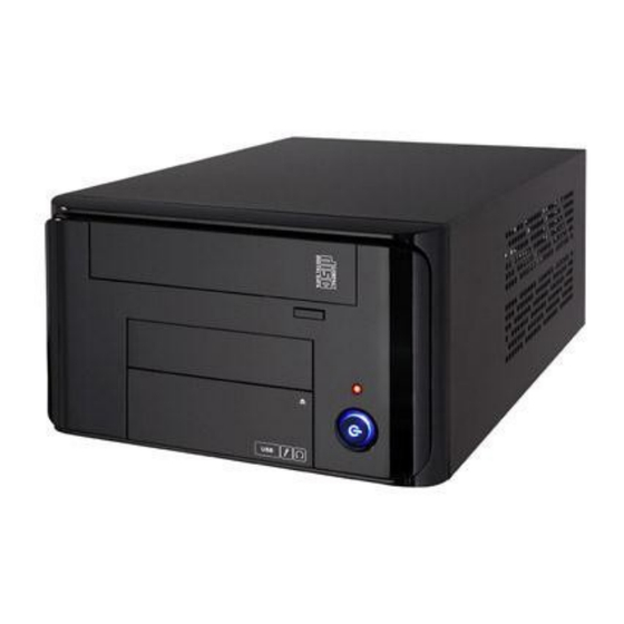
Page 25: Front Panel
Front panel The server displays a simple yet stylish front panel with easily accessible features. The power and reset buttons, LED indicators, optical drive, and two USB ports are located on the front panel. The combo power, power indicator and reset button, LED indicators, DVD-ROM drive, audio (microphone and earphone) and USB ports are located on the front panel. -
Page 26: Rear Panel
6. Combination power switch and power indicator Rear panel The rear panel includes a slot for the motherboard rear I/O ports, expansion slots, a chassis lock and intrusion switch, a vent for the system fan, and power supply module. Figure 2: Rear Panel 1. - Page 27 Figure 3: Rear Panel I/O Figure 4: Audio Connections...
-
Page 28: Internal
Internal The server includes the basic components as shown. Figure 5: Internal View 1. Optical drive (DVD) 2. SSD module (Hidden under DVD) 3. Expansion Slot PCIe 3.0 4. 250W Single Power supply unit: Turn off the system power and detach the power supply before removing or replacing any system component. -
Page 29: Front Panel Leds
Front panel LEDs LAN LEDs Figure 6: LAN LEDs... -
Page 30: Configuration Plan
Chapter 2 Before Deployment Configuration Plan Thoroughly research and establish an installation and configuration plan for your specific network environment. You should also plan how you want to configure your storage. Gather information The system has the ability to be set with one or multiple IP addresses. The simple online configuration procedures will allow you to set-up your system on your network using these IP addresses. -
Page 31: Packing Checklist
Check your system package for the following items: Model Name AS 61SSD Chassis: AS61 Mini tower chassis Component AS61 Mini tower 1 x 250W Power Supply Accessories: 1 x AS 61SSD Series User's Guide 1 x RASILIENT SYSTEMS Quick Start Guide 1 x AC Power Cable...
Need help?
Do you have a question about the ApplianceStor 61 and is the answer not in the manual?
Questions and answers