Table of Contents
Advertisement
Quick Links
Advertisement
Table of Contents

Related Manuals for Rasilient ApplianceStor 70v2


Summary of Contents for Rasilient ApplianceStor 70v2
- Page 1 ApplianceStor 70v2 Performance Storage Server User Manual Version 1.3 April 2020...
- Page 2 Copyright Notice All rights, including copyright, in the content of this manual are owned or controlled by RASILIENT and protected by copyright. No part of this document may be photocopied, reproduced, or translated into another language without the prior written consent of RASILIENT Systems, Inc.
-
Page 3: Table Of Contents
Table of Contents Conventions ............5 Safety Symbols .................. 5 Safety Precautions ................6 Regulatory and Integration Information ....8 Product Safety Compliance ..............8 Product EMC Compliance ..............8 Power Cords ..................10 Introduction ............12 Audience Assumptions ..............12 About This Guide ................ - Page 4 Rail kit dimensions ................24 Protective Film .................. 24 Disk drives ..................25 Redundant power supply module ............27 Tables Table 1: Safety Compliance .......................... 8 Table 2: European Union Compliance ......................9 Table 3: Manual Organization ........................12 Table 4: Packing Check List........................19...
- Page 5 About This Manual Conventions Safety Symbols Safety Precautions Regulatory and Integration Information...
-
Page 6: Conventions
Conventions To make sure that you perform certain tasks properly, take note of the following symbols used throughout this manual. Safety Symbols The following symbols are placed on some components of the system to alert the user to potential hazards, WARNING: Electric Shock Hazard –... -
Page 7: Safety Precautions
Safety Precautions Technician Notes Only authorized technicians should attempt to repair this equipment. Before installing this system, carefully read all the manuals included with the system. All repair procedures allow only module replacement. Because of the complexity of the individual boards and sub-assembles, no one should attempt to make repairs at the component level or make modifications to any printed wiring board. - Page 8 To properly ventilate the system, you must provide at least 7.6 cm of clearance at the front and back of the system. To reduce the risk of personal injury or damage to equipment, always ensure that the rack is adequately stabilized prior to extending a component outside the rack.
-
Page 9: Regulatory And Integration Information
Regulatory and Integration Information Regulatory Compliance Identification Numbers For the purpose of regulatory compliance certifications and identification, this system is assigned a serial number. This system serial number can be found on the product label, along with the required approval markings and information. -
Page 10: Table 2: European Union Compliance
This equipment has been tested and found to comply with the limits for a Class A digital device, pursuant to Part 15 of the FCC Rules. These limits are designed to provide reasonable protection against harmful interference when the equipment is operated in a commercial environment. This equipment generates, uses, and can radiate radio frequency energy and, if not installed and used in accordance with the instructions, may cause harmful interference to radio communications. -
Page 11: Power Cords
Taiwanese Notice Power Cords The power cord set included in the system meets the requirements for use in the country where the system was purchased. If this system is to be used in another country, contact your sales representative to purchase a power cord that is approved for use in that country. The power cord must be rated for the product and for the voltage and current marked on the product's electrical ratings label. - Page 12 Chapter 1 Chapter 1 Introduction Introduction Audience Assumptions About This Guide Product Introduction System Specifications...
-
Page 13: Introduction
Simple The ApplianceStor 70v2 integrates VMS (Video Management Software) and storage into a simple to use, high performance video surveillance storage server solution. This eliminates the cost of the VMS server, significantly reduces cabling and the nightmare of integrating VMS, OS, commodity server and storage, while significantly reduces the overall solution cost. -
Page 14: Reliable
Providers. All major supported Video Analytic Software providers are prequalified. More are continually added to ensure the widest possible certification coverage. Optimized The ApplianceStor 70v2 is optimized for the Video Surveillance applications and market place. It provides the performance and capacity for the most demanding megapixel installations. Easy AS70V2 provides effortless installation, management and administration. -
Page 15: System Specification
System Specification Core Technology CPU Type Xeon® E-2134 Socket LGA1151 Core Logic Intel® C242 Chipset Memory size up to 64GB Memory type DDR4 2400 ECC UDIMM Expansion Expansion Slot : 2 (not available for user) Slot Type: 1xPCI-E x16 slot(Gen3 X8 Link)(Full-Height/Half- Length) 1 xPCI-E x8 slot (Gen3 X8 Link)(Full-Height/Half- Length) - Page 16 2 x USB 3.1 ports and 4x 3.0 USB port, (Front x 2, Rear x 4) 1 x VGA port Management Solution Remote KVM-iKVM for KVM-over-IP support ASWM Enterprise Compliance Safety US/Canada (UL1950-CSA950) Europe (CE, EN55022 US (FCC, CFR47 Part 15, Class A) Europe (CE, EN55022 &...
-
Page 17: System Layout
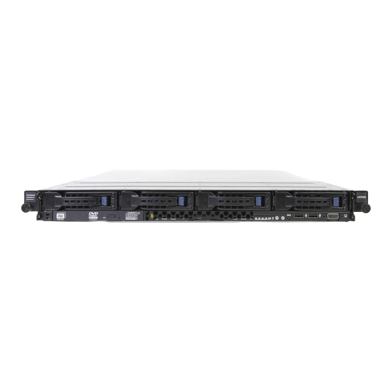
System Layout Front panel The AS70V2 displays a simple yet stylish front panel with easily accessible features. The power and reset buttons, LED indicators, and USB port are located on the front panel. Figure 1: Front Panel Front Panel LEDs Icon Display status Description Power LED... -
Page 18: Rear Panel
Rear Panel The rear panel includes the expansion slots, system power sockets, and rear fans. The I/O shields with openings for the rear panel connectors on the motherboard are also placed in the rear panel. Figure 2: Rear Panel LAN Port LEDs... -
Page 19: Internal
Internal The AS70V2 server includes the basic components as shown. Turn off the system power and detach the power supply before removing replacing any system component. WARNING HAZARDOUS MOVING PARTS KEEP FINGERS AND OTHER BODY PARTS AWAY... -
Page 20: Before You Begin
Chapter 2 Before You Begin Before You Begin Thoroughly research and establish an installation and configuration plan for your specific network environment. You should also plan how you want to configure your storage. Gather information The system has the ability to be set with one or multiple IP addresses. The simple online configuration procedures will allow you to set-up your system on your network using these IP addresses. - Page 21 Chapter 3 Hardware Installation Rail Kit Installation Installing in a Rack Installing Drives...
-
Page 22: Hardware Installation
Hardware Installation Tool-less Friction Rail Kit The tool less design of the rail kit allows you to easily install the rack rails into the server rack without the need for additional tools. The kit also comes with a metal stopping bracket that can be installed to provide additional support and stability to the server. - Page 23 Follow steps 2 to 4 if the depth of your server rack exceeds 850mm, if the depth of your server rack is less than 850mm, please skip steps 2 to 4 and proceed with step 5. Slightly slide out and extend the right rack rail, then prepare one of the bundled rail components. Rail component Align the rail component with the right rack rail and secure it using four (4) bundled screws.
- Page 24 6. Secure the rail components to the rail using the bundled screws. Press the spring lock ( ) then insert the studs into the selected square mounting holes on the rack post. Press the spring lock on the other end of rail then insert the stud into the mounting hole on the rack post.
-
Page 25: Rail Kit Dimensions
Rail kit dimensions 43.6mm 900mm 43.6mm 589mm Protective Film A protection film is pre-attached to the system cover before shipping. Please remove the protection film before turning on the system for proper heat dissipation. -
Page 26: Disk Drives
Disk drives The system supports four hot-swap disk drives . The disk drive installed on the drive tray connects to the motherboard SATA/SAS ports via the SATA/SAS backplane. Disk Tray installation Insert the drive tray and HDD assembly all the way into the depth of the bay until just a small fraction of the tray edge protrudes. - Page 27 Firmly hold the tray lever and pull the drive tray out of the bay.
-
Page 28: Redundant Power Supply Module
Redundant power supply module To replace a failed redundant power supply module: Hold the power supply module lever and press the PSU latch (A) then pull the power supply module (B) out of the system chassis. module lever PSU latch Get the replacement power supply module.Insert the replacement power supply module into the chassis then push it inwards until the latch locks into place.
Need help?
Do you have a question about the ApplianceStor 70v2 and is the answer not in the manual?
Questions and answers