Table of Contents
Advertisement
Quick Links
Advertisement
Table of Contents

Subscribe to Our Youtube Channel
Related Manuals for Pilz PZW Series


Summary of Contents for Pilz PZW Series
- Page 1 Safe monitoring relays Operating Manual-19157-EN-07...
- Page 2 Preface This document is the original document. All rights to this documentation are reserved by Pilz GmbH & Co. KG. Copies may be made for the user's internal purposes. Suggestions and comments for improving this documenta- tion will be gratefully received.
-
Page 3: Table Of Contents
Contents Introduction Validity of documentation Using the documentation Definition of symbols Safety Intended use Safety regulations Safety assessment Use of qualified personnel Warranty and liability Disposal For your safety Unit features Safety features Block diagram/terminal configuration Types: AC Types: DC Function description Installation Wiring... -
Page 4: Introduction
Introduction Validity of documentation This documentation is valid for the product PZW. It is valid until new documentation is pub- lished. This operating manual explains the function and operation, describes the installation and provides guidelines on how to connect the product. Using the documentation This document is intended for instruction. -
Page 5: Safety
INFORMATION This gives advice on applications and provides information on special fea- tures. Safety Intended use The unit operates as a pulse relay in accordance with EN ISO 12100:2010 section 6.2.11.10, 6.3.2.4 and 3.28.9 (inching circuit for limited movement of hazardous machine components during installation, set up and positioning) in safety circuits in accordance with VDE 0113-1 and IEC 60204-1 The unit is designed for use with... -
Page 6: Safety Regulations
Safety regulations Safety assessment Before using a device it is necessary to perform a safety assessment in accordance with the Machinery Directive. Functional safety is guaranteed for the product as a single component. However, this does not guarantee the functional safety of the overall plant/machine. In order to achieve the re- quired safety level for the overall plant/machine, define the safety requirements for the plant/machine and then define how these must be implemented from a technical and organ- isational standpoint. -
Page 7: For Your Safety
For your safety The unit meets all the necessary conditions for safe operation. However, please note the following: Note for overvoltage category III: If voltages higher than low voltage (>50 VAC or >120 VDC) are present on the unit, connected control elements and sensors must have a rated insulation voltage of at least 250 V. -
Page 8: Block Diagram/Terminal Configuration
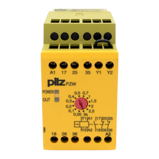
Block diagram/terminal configuration Types: AC : 110 - 120 VAC; Order no. 774015, 774044 : 230 V AC; Order no. 774017, 774048 *Insulation between the non-marked area and the relay contacts: Basic insulation (over- voltage category III), Protective separation (overvoltage category II) Types: DC : 24 VDC;... -
Page 9: Function Description
Function description The unit is ready for operation when the feedback loop Y1-Y2 is closed. Input circuit closed (supply voltage is present) "POWER" LED is illuminated. The safety contact 17-18 will be closed immediately and the auxiliary contacts 25-26, 35-36 will open, time sequence starts. The "OUT" LED is lit. -
Page 10: Installation
Installation The unit should be installed in a control cabinet with a protection type of at least IP54. Use the notch on the rear of the unit to attach it to a DIN rail (35 mm). When installed vertically: Secure the unit by using a fixing element (e.g. retaining bracket or end angle). -
Page 11: Preparing For Operation
Preparing for Operation Connection Supply voltage Input circuit is driven by connect- ing U Without feedback loop monitor- Feedback loop With feedback loop monitoring Link or contacts from external con- tactors Application example S31 S32 S11 S12 S13 S14 17 25 35 Y1 Y2 PNOZ X3 26 36 S21 S22 S33 S34... -
Page 12: Operation
Operation When the relay outputs are switched on, the mechanical contact on the relay cannot be tested automatically. Depending on the operational environment, measures to detect the non-opening of switching elements may be required under some circumstances. When the product is used in accordance with the European Machinery Directive, a check must be carried out to ensure that the safety contacts on the relay outputs open correctly. -
Page 13: Dimensions In Mm
Dimensions in mm 75 (2.95") 45 (1,77") 87 (3.42") Technical details Order no. 774015 – 774019 See below for more order numbers General 774015 774017 774019 CE, EAC (Eurasian), CE, EAC (Eurasian), CE, EAC (Eurasian), Approvals TÜV, cULus Listed TÜV, cULus Listed TÜV, cULus Listed Electrical data 774015... - Page 14 Relay outputs 774015 774017 774019 Number of output con- tacts Safety contacts (N/O), delayed Auxiliary contacts (N/ C), delayed Max. short circuit current 1 kA 1 kA 1 kA Utilisation category In accordance with the standard EN 60947-4-1 EN 60947-4-1 EN 60947-4-1 Utilisation category of safety contacts...
- Page 15 Relay outputs 774015 774017 774019 Utilisation category in ac- cordance with UL Voltage 240 V AC G. P. 240 V AC G. P. 240 V AC G. P. With current Voltage 24 V DC Resistive 24 V DC Resistive 24 V DC Resistive With current Pilot Duty B300, R300...
- Page 16 Environmental data 774015 774017 774019 Climatic suitability Humidity 93 % r. h. at 40 °C 93 % r. h. at 40 °C 93 % r. h. at 40 °C Condensation during op- eration Not permitted Not permitted Not permitted EN 60947-5-1, EN EN 60947-5-1, EN EN 60947-5-1, EN 61000-6-2, EN 61326-3-1...
- Page 17 Mechanical data 774015 774017 774019 Dimensions Height 87 mm 87 mm 87 mm Width 45 mm 45 mm 45 mm Depth 121 mm 121 mm 121 mm Weight 350 g 350 g 255 g Order no. 774042 – 774048 General 774042 774044 774048...
- Page 18 Relay outputs 774042 774044 774048 Utilisation category of safety contacts AC1 at 240 V 240 V 240 V Min. current 0,01 A 0,01 A 0,01 A Max. current Max. power 1500 VA 1500 VA 1500 VA DC1 at 24 V 24 V 24 V Min.
- Page 19 Relay outputs 774042 774044 774048 External contact fuse pro- tection, safety contacts In accordance with the standard EN 60947-5-1 EN 60947-5-1 EN 60947-5-1 Max. melting integral 240 A²s 240 A²s 240 A²s Blow-out fuse, quick Blow-out fuse, slow Blow-out fuse, gG Circuit breaker 24V AC/DC, characteristic External contact fuse pro-...
- Page 20 Environmental data 774042 774044 774048 Vibration In accordance with the standard EN 60068-2-6 EN 60068-2-6 EN 60068-2-6 Frequency 10 - 55 Hz 10 - 55 Hz 10 - 55 Hz Amplitude 0,35 mm 0,35 mm 0,35 mm Airgap creepage In accordance with the standard EN 60947-1 EN 60947-1...
-
Page 21: Safety Characteristic Data
Safety characteristic data NOTICE You must comply with the safety characteristic data in order to achieve the required safety level for your plant/machine. Operating EN ISO EN ISO EN 62061 EN 62061 IEC 61511 IEC 61511 EN ISO mode 13849-1: 13849-1: 13849-1: SIL CL [1/h] 2015... -
Page 22: Supplementary Data
Supplementary data Service life graph The service life graphs indicate the number of cycles from which failures due to wear must be expected. The wear is mainly caused by the electrical load; the mechanical load is negli- gible. Switching current (A) Example Inductive load: 0.2 A Utilisation category: AC15... -
Page 23: Ec Declaration Of Conformity
This product/these products meet the requirements of the directive 2006/42/EC for ma- chinery of the European Parliament and of the Council. The complete EC Declaration of Conformity is available on the Internet at www.pilz.com/support/downloads. Representative: Norbert Fröhlich, Pilz GmbH & Co. KG, Felix-Wankel-Str. 2, 73760 Ost- fildern, Germany Operating Manual PZW... - Page 24 Back cover Support Technical support is available from Pilz round the clock. Americas Australia Scandinavia Brazil +61 3 95600621 +45 74436332 +55 11 97569-2804 Spain Canada Europe +34 938497433 +1 888-315-PILZ (315-7459) Austria Switzerland Mexico +43 1 7986263-0 +41 62 88979-30...
Need help?
Do you have a question about the PZW Series and is the answer not in the manual?
Questions and answers