Table of Contents
Advertisement
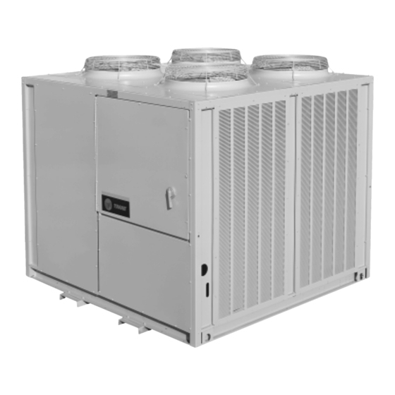
Remote Air Cooled Condensers
Models
"J" and Later Design Sequence
CAUC-C20
CAUC-C40
CAUC-C25
CAUC-C50
CAUC-C30
CAUC-C60
© 2008 Trane All rights reserved
http://www.trane.com
TM
Installation
Operation
Maintenance
L
b i
a r
y r
P
o r
d
u
t c
S
e
t c
o i
n
Product
Model
i L
e t
a r
u t
e r
T
y
p
e
S
e
q
u
e
n
c
e
Date
File No.
S
u
p
e
s r
e
d
e
s
Since the manufacturer has a policy of continuous product
improvement, it reserves the right to change specifications and
design without notice.
CAUC-IOM-7
n I
t s
l l a
t a
o i
/ n
SV-UN-S/S-CAUC-IOM-7 10/08
Note: The installation of this equipment must
comply with all National, State, and Local
Codes.
S
e
v r
c i
e
i L
e t
a r
u t
e r
R
e
r f
g i
r e
t a
o i
n
Air Cooled Condenser
CAUC
O
p
r e
t a
o i
/ n
M
a
n i
e t
n
a
n
c
e
7
October 2008
December 2001
Advertisement
Table of Contents

Subscribe to Our Youtube Channel
Related Manuals for Trane CAUC-C20


Summary of Contents for Trane CAUC-C20
- Page 1 "J" and Later Design Sequence Codes. CAUC-C20 CAUC-C40 CAUC-C25 CAUC-C50 CAUC-C30 CAUC-C60 Since the manufacturer has a policy of continuous product © 2008 Trane All rights reserved improvement, it reserves the right to change specifications and design without notice. http://www.trane.com...
-
Page 2: About The Manual
About The Manual Literature Change History It is important that periodic maintenance be performed to help assure trouble free operation. A maintenance schedule is provided at the end of this manual. Should equipment CAUC-IOM-7 (December 2001) failure occur, contact a qualified service organization with First issue of manual;... -
Page 3: Table Of Contents
Table of Contents Section One Discharge (Hot Gas) Lines ......... 18 Discharge Line Components ........19 About The Manual Making Refrigerant Connections ........19 Literature Change History ..........2 Brazing Procedures ............19 Overview of Manual ............2 Leak Testing Procedure ..........20 Field Installed Power Wiring .......... -
Page 4: General Information
General Information Model Number Description When ordering replacement parts or requesting service, be All Trane products are identified by a multiple-character sure to refer to the specific model number, serial number, model number that precisely identifies a particular type of and DL number (if applicable) stamped on the unit name- unit. -
Page 5: Unit Component Layout And "Shipwith" Locations
General Information (Continued) Unit Component “Layout” and “Shipwith” Locations (60 Ton Unit Illustrated) -
Page 6: Installation
Follow the instructions under “Unit Isolation” for proper iso- evidence that the damage did not occur after delivery. lator placement and installation. [ ] Notify the appropriate Trane office before installing or re- Check with a roofing contractor for proper waterproofing pairing a damaged unit. - Page 7 Installation (Continued) Figure 3-1 Typical Installation Clearances for Single, Multiple or Pit Applications...
- Page 8 Figure 3-2 CAUC-C20 Unit Dimensional Data & Recommended Clearances...
- Page 9 Figure 3-2 (Continued) CAUC-C25 Unit Dimensional Data & Recommended Clearances...
- Page 10 Figure 3-2 (Continued) CAUC-C30 Unit Dimensional Data & Recommended Clearances...
-
Page 14: Rigging
Installation (Continued) Table 3-1 Typical Unit Weights & Point Loading Data Operating Unit Weight on Isolator @ Mounting Location Unit Weight Size 1146 1343 1190 1393 1302 1594 2048 2379 2280 2672 2465 3036 Notes: 1. Mounting locations correlate with those shown in point loading illustration. Location of Center of Shipping Gravity =... -
Page 15: Unit Isolation
Installation (Continued) Neoprene Isolators Rigging Install the neoprene isolators at each unit mounting (load) point, using the following procedure: A Rigging illustration and Center-of-Gravity dimensional data table is shown in Figure 3-3. Refer to the typical unit 1. Elevate the unit (one side at a time) to allow access to operating weights table before proceeding. -
Page 16: Spring Isolators
Installation (Continued) Spring Isolators 5. Make minor clearance adjustments by turning the isola- Install the spring isolators at each unit mounting (load) point tor leveling bolt (Figure 3-5) clockwise to increase the using the following procedure: clearance and counterclockwise to decrease the clear- ance. -
Page 17: General Unit Requirements
[ ] Check the unit for shipping damage and material short- [ ] Install proper grounding wires to an earth ground. age; file a freight claim and notify Trane office. Field Installed Control Wiring [ ] Verify that the installation location of the unit will provide the required clearance for proper operation. -
Page 18: Refrigerant Piping
Trane recommends that the Refrigerant Line Sizing pro- Liquid Line Solenoid Valves gram in the "Trane C.D.S. Application Toolbox" be used to size the refrigerant lines. This program supersedes the line Liquid line solenoid valves are not recommended on units sizing tables in both the Trane Reciprocating Refrigeration when they are connected to DX coils. -
Page 19: Discharge Line Components
Installation (Continued) present, relieve the pressure before attempting to unsweat A double riser system may be necessary to meet the dis- the “seal” caps. If refrigerant connections are not capped, charge line velocity requirements. but are “spun-end” tubes, use a tubing cutter to remove the end from the pipe. -
Page 20: Leak Testing Procedure
Note: All field installed wiring must conform to NEC pressure during leak testing. guidelines as well as State and Local codes. Trane condensing units are shipped with a Nitrogen hold- Verify that the power supply available is compatible with the unit’s nameplate ratings. The available supply power must ing charge. - Page 21 Installation (Continued) Table 3-3 Customer Connection Wire Range Table 3-4 Unit Electrical Data Allowable Minimum Maximum Dual Condenser Fan Motors Unit Rated Voltage Circuit Fuse Element Size Voltage Range Ampacity Size Fuse Qty. (Each) (Each) (Each) (Each) 200/230/60/3 180-220/208-254 20.7 460/60/3 416-508 575/60/3...
- Page 22 Installation (Continued) Figure 3-6 Typical CAUC C20 through C60 Ton Field Wiring Diagram Power Wire Sizing and Protection Device Equations To correctly size the main power wiring for the unit, use the appropriate calculation(s) listed below. Read the load definitions that follow and use Calculation #1 for determining the MCA (Minimum Circuit Ampacity), MOP (Maximum Over current Pro- tection), and RDE (Recommended Dual Element fuse size) for each unit.
-
Page 23: Field Installed Control Wiring
2. Install an additional jumper between terminals 1TB3-6 CCAD Package Chiller Interface and 1TB3-7 in the CAUC control panel. The Unit Control Module (UCM) within the Trane Model (Circuit #2 - 40 through 60 Ton Units) CCAD package chiller is designed to control the CAUC con- 3. -
Page 26: System Pre-Start Procedures
System Pre-Start Procedures Use the checklist provided below in conjunction with the and suction line access valve). Follow the pump “General Unit Requirement” checklist” to ensure that the manufacturer’s directions for the proper methods of using unit is properly installed and ready for operation. Be sure to the vacuum pump. - Page 27 System Pre-Start Procedures (Continued) If a leak is encounter, repair the system and repeat the Figure 4-1 evacuation process until the recommended vacuum is ob- Typical Vacuum Pump Hookup tained. Once the system has been evacuated, break the vacuum with refrigerant, and complete the remaining “Pre-Start Pro- cedures"...
-
Page 28: Voltage Imbalance
System Pre-Start Procedures (Continued) Voltage Imbalance Electrical Phasing Excessive three phase voltage imbalance between phases Proper electrical phasing can be quickly determined and will cause motors to overheat and eventually fail. The maxi- corrected before starting the unit by using an instrument mum allowable voltage imbalance is 2%. -
Page 29: System Start-Up
2. 1S36 and 1S37 normally-closed contacts open on ambient temperature drop to 65 F. Contacts reclose on ambient temperature rise to 67.5 3. Above data does not apply when units are interfaced with Trane Model CCAD package chillers. UCM for the CCAD unit commands fan control. -
Page 30: Verifying Proper Condenser Fan Rotation
System Start-Up (Continued) Figure 5-1 Condenser Fan Locations Verifying Proper Condenser Fan Rotation All Fans are Rotating Backwards; 1. “Open” the field supplied disconnect switch or circuit pro- 1. Turn the field supplied disconnect switch or circuit protec- tector switch that provides power to the compressor unit tor switch that provides power to the condensing unit to and lock it in the “Off”... -
Page 31: Low Ambient Damper Adjustment
Table 5-4. Notes: 1. CAUC-C20 - C30 are single-circuit units If the pressure within the system equalizes with the pres- CAUC-40 - C60 are dual-circuit units sure in the charging cylinder before charging is com- 2. - Page 32 System Start-Up (Continued) Table 5-4 Liquid Line & Drier Refrigerant Requirements Liquid Liquid Sporlan Drier Line Line Part Refrigerant O.D. Charge Charge 5/8" 1.827 C-305-S 1 lb. - 1 oz. 3/4" 2.728 C-307-S 1 lb. - 1 oz. C-417-S 1 lb. - 8 oz. 7/8"...
- Page 33 Blank...
- Page 36 Figure 5-3 Typical Control Panel Connections Diagram for 20 through 60 Ton Units...
-
Page 38: Service And Maintenance
Service and Maintenance Fuse Replacement Data Table 6-1 lists the replacement fuses for the control circuit and Transformers. Table 6-1 Fuse Replacement Data Monthly Maintenance Before completing the following checks, turn all system con- Note: Over lubrication can be just as harmful as not trol circuit switches to the “Off”... -
Page 39: Coil Cleaning
Service and Maintenance (Continued) 3. Straighten any bent coil fins with a fin comb. System operation [ ] Close the main power disconnect switch for the Con- 4. Mix the detergent with water according to the densing Unit and all system support equipment. Turn all system control circuit switches to the “On”... -
Page 40: Index
Low Ambient Dampers ............29 low ambient option ............. 31 Air Handling Equipment ............. 38 Low Ambient Thermostat 2 ..........9 CAUC-C20 Unit Dimensional Data ........8 Minimum Starting Ambient ..........31 See Figure 3-2 See Table 5-2 CAUC-C25 Unit Dimensional Data ........9 Minimum Vertical Line Velocities ........ - Page 41 WARRANTY AND LIABILITY CLAUSE COMMERCIAL EQUIPMENT RATED 20 TONS AND LARGER AND RELATED ACCESSORIES PRODUCTS COVERED - This warranty* is extended THE WARRANTY AND LIABILITY SET by American Standard Inc. and applies only to com- FORTH HEREIN ARE IN LIEU OF ALL mercial equipment rated 20 Tons and larger and OTHER WARRANTIES AND LIABILITIES, related accessories.
Need help?
Do you have a question about the CAUC-C20 and is the answer not in the manual?
Questions and answers