Table of Contents
Advertisement
Quick Links
Advertisement
Table of Contents

Subscribe to Our Youtube Channel
Related Manuals for SOLE S150

Summary of Contents for SOLE S150
- Page 1 SOLAR COLLECTORS INSTALLATION MANUAL MODELS: S150 – S200 – S230 – S260...
- Page 2 Page 2 of 24...
-
Page 3: Table Of Contents
INDEX PAGE 1. Presentation …………………………………………………………………….. 2. Parts Included …………………………………………………………………… 4 2.1. Solar Collectors ……………………………………………………………. 4 2.2. Support Frame ……………………………………………………………. 2.3. Connectors …………………………………………………………………. 7 3. Placement of the Collectors ……………………………………………………. 8 4. Bank of Collectors ………………………………………………………………. 9 5. Flat Roof Installation ……………………………………………………………. 13 5.1. -
Page 4: Presentation
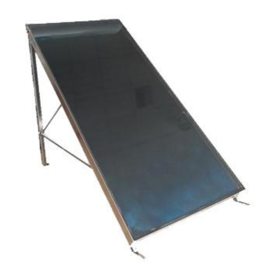
The main technical characteristics of the collectors are indicated below (figure no. 1) TYPE WEIGHT DIMENSIONS (mm) S150 27,30kg 1540 1010 1458 1815... - Page 5 Flow recommended 40 litres/h/m² Content of liquid S150 = 0,85ltr; S200 = 0,95 ltr; S230 = 1,20ltr; S260 = 1,30ltr Figure 1. Characteristics of solar collector The manufacturing of the solar collector follow strict quality criteria and is certified by ISO 9001:2008.
-
Page 6: Support Frame
2.2. Support Frame There are two sets of support frames for a single collector (EST1) or for two collectors (EST2). Depending on the bank of solar collectors chosen, the appropriate number of support frames will be provided for one or two collectors. Table 1 shows the sets of support frames necessary for different banks of solar collectors. -
Page 7: Connectors
Figure 4. Support frame components EST2 for two solar collectors The support frames allow the installation of the solar collectors with different inclinations (45, 40, 35 or 30 degrees) using the same profiles and accessories, by choosing properly the fixing holes. 2.3. -
Page 8: Placement Of The Collectors
3. Placement of the Collectors The choice of location, inclination and orientation of the solar collectors has to be determined at the design stage of the installation. The installation of the solar collectors in the building should be carried out respecting the instructions of the person in charge of the project, who should have taken into consideration the effect of the orientation, inclination and possible shadows in the calculation of benefits of the solar system. -
Page 9: Bank Of Collectors
1 to 6 units and for different angles of inclination. Additionally, there should be sufficient space around the banks of collectors to perform with comfort the hydraulic connections. Figure 7. A Single Collector TYPE S150 960mm S200 960mm S230... - Page 10 Figure 8. Bank of Two Solar Collectors TYPE S150 1980mm 890mm 555mm 960mm S200 1980mm 890mm 555mm 960mm S230 2390mm 1435mm 477,5mm 1165mm S260 2536mm 1435mm 550,5mm 1238mm Figure 9. Bank of Three Solar Collectors TYPE S150 3000mm 890mm 555mm...
- Page 11 Figure 10. Bank of Four Solar Collectors TYPE S150 4020mm 890mm 555mm 960mm 1150mm S200 5020mm 890mm 555mm 960mm 1150mm S230 4840mm 1435mm 477,5mm 1165mm 1015mm S260 5132mm 1435mm 550,5mm 1238mm 1161mm Figue 11. Bank of Five Solar Collectors TYPE...
- Page 12 Figure 12. Bank of Six Solar Collectors TYPE S150 6060mm 890mm 955 mm 960mm 1150mm Figure 13. Dimensions of the banks of collectors depending on the inclination.(The above dimensions apply to all sizes of collectors) Page 12 of 24...
-
Page 13: Flat Roof Installation
5. Flat Roof Installation Next it will be described the procedure for installing a bank of two solar collectors on a flat roof. The formation of more banks of collectors is done simply by adding the support frames EST1 or EST2 when necessary. 5.1. -
Page 14: Installation Of Vertical Legs A3 And The Long Cross Pieces X1/1/X2
5.2. Installation of the vertical legs A3 and the Long cross pieces X1/X2 Place the two long crosspieces X1 or X2 forming an X, with the convex part of the profiles and link them into contact with each other through a bolt M10x20 with nut and washer, without tighten it yet. -
Page 15: Installation Of Vertical Legs A3 And The Longitudinal Profiles D3
5.3. Installation of the vertical legs A3 and the longitudinal profiles D3 Lift the legs A3 coupled with the X formed with the long crosspieces X1 or X2 until you place them vertically. Lift the rear part of the longitudinal profiles D3 coupled with the cross profiles E1 or E2 and join to the vertical legs A3, using two holes depending on the inclination that should be given to the collectors (Fig. -
Page 16: Placement Of Solar Collectors
5.4. Placement of Solar Collectors Place one of the solar collectors in the support frame, place it first on the lower profile cross-E1 or E2 and then on the higher profile cross- E1 or E2. Adjust the position of the solar collector in the structure, so that matches the holes in the structure of the holes in the rear part of the collector (Figure 17). -
Page 17: Tile Roof Installation
6. Tile roof installation The assembly of solar collectors on a tile roof is done in a manner similar to that described above, with a different position of the vertical legs A3 that have to be placed horizontally underneath the E1/E2 in a parallel manner. The crosspieces X1 or X2 and X3 shorts are not needed for tile roof installation. - Page 18 In each group of solar collectors two stop valves should be installed at the entrance and exit to allow the hydraulic isolation of the rest of the circuit and a safety valve (figure 20). The solar collectors reach high temperatures, especially in periods of great sunshine and low energy consumption, which can cause significant expansion of the materials.
- Page 19 Figure 21. The pipes must be insulated according to existing regulations. The thickness of the insulation material must be at least 30 mm for a material with conductivity equal to 0.040 W/mºK. The insulation material must be capable of withstanding pipe surface temperatures higher than 120 °...
-
Page 20: Lightning Protection
The primary circuit of the solar collectors must have at least a thermometer and a manometer to permit recording of the temperature and the pressure of the circuit. Before the final filling of the primary circuit, internal washing with domestic water should be carried out to remove any dirt or rests and pressure test should be carried out to verify the sealing of all, without exceeding the maximum pressure allowed by solar collectors. -
Page 21: Care And Maintenance Program
10. Care and Maintenance Program • The collectors should be subject to periodic visual inspections. If it appears that excessive dirt has been accumulated on the glass of the collectors, then it must be cleaned. This operation should take place during the morning, before 10:00 am or in the afternoon after the 18:00 pm, checking before that the collectors are not too hot. - Page 22 NOTES Page 22 of 24...
- Page 23 NOTES Page 23 of 24...
- Page 24 Published: June 2015 Version 1 SOLE S.A. SOLAR DOMESTIC APPLIANCES MANUFACTURER Lefktron & Laikon Agonon, 136 71 Acharnai – Athens – Greece Tel.: (+30210) 2389500 • Fax: (30210) 2389502 Email: export@sole.gr •www.eurostar-solar.c Page 24 of 24...
Need help?
Do you have a question about the S150 and is the answer not in the manual?
Questions and answers