
Related Manuals for WAGO 750-559


Summary of Contents for WAGO 750-559
- Page 1 Fieldbus Independent I/O Modules 4 AO DC 0-10 V 750-559(/xxx-xxx) Manual Version 1.0.6...
- Page 2 • General Copyright © 2007 by WAGO Kontakttechnik GmbH & Co. KG All rights reserved. WAGO Kontakttechnik GmbH & Co. KG Hansastraße 27 D-32423 Minden Phone: +49 (0) 571/8 87 – 0 Fax: +49 (0) 571/8 87 – 1 69 E-Mail: info@wago.com...
-
Page 3: Table Of Contents
Symbols ....................5 Number Notation..................5 Safety Notes ..................... 6 Scope ......................6 2 I/O Modules ....................7 Analog Output Modules ................7 2.1.1 750-559(/xxx-xxx) [4 AO DC 0-10 V]..........7 2.1.1.1 Variations..................7 2.1.1.2 View....................7 2.1.1.3 Description..................8 2.1.1.4... -
Page 4: Important Comments
WAGO Kontakttechnik GmbH & Co. KG declines all liability resulting from improper action and damage to WAGO products and third party products due to non-observance of the information contained in this manual. -
Page 5: Symbols
More information References on additional literature, manuals, data sheets and internet pages. 1.3 Number Notation Number Code Example Note Decimal normal notation Hexadecimal 0x64 C notation Binary '100' within inverted commas, '0110.0100' nibble separated with dots WAGO-I/O-SYSTEM 750 I/O Modules... -
Page 6: Safety Notes
Do not use any contact spray. The spray may impair the functioning of the contact area. The WAGO-I/O-SYSTEM 750 and its components are an open system. It must only be assembled in housings, cabinets or in electrical operation rooms. Access must only be given via a key or tool to authorized qualified personnel. -
Page 7: O Modules
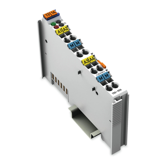
Function Error A1 A2 Datacontacts AO 1 AO 2 Common Common (ground) (ground) A3 A4 AO 3 AO 4 Common Common (ground) (ground) 750-559 Power jumper contacts Fig. 2.1.1-1: 4- Channel Analog Output Module 750-559 g055900e WAGO-I/O-SYSTEM 750 I/O Modules... -
Page 8: Description
Description 2.1.1.3 Description The analog output module 750-559 creates a standardized signal of 0-10 V. The module has four output channels and enables, for example, the direct wiring of four 2-conductor actuators to the connections AO 1 and Common (ground) or AO 2, AO 3, AO 4 and each with Common (ground). The signals are transmitted via AO 1, AO 2, AO 3 or AO 4. -
Page 9: Display Elements
2.1.1.5 Schematic Diagram Logic AO 1 AO 2 Common Function 270 pF (ground) Error AO 3 AO 4 10 nF Common Common (ground) (ground) 750-559 Fig. 2.1.1-3: 4-Channel Analog Output Module 750-559 g055901e WAGO-I/O-SYSTEM 750 I/O Modules... -
Page 10: Technical Data
10 • 750-559(/xxx-xxx) [4 AO DC 0-10 V] Technical Data 2.1.1.6 Technical Data Module Specific Data Number of outputs Voltage supply via system voltage DC/DC Current consumption . (internal) 125 mA Signal voltage 0V ... 10 V Load impedance > 5 kΩ... -
Page 11: Process Image
System Description 2.1.1.7 Process Image The analog output module 750-559 transmits 16-bit data and 8 status bits per channel. The digitalized output value is transmitted in a data word (16 bits) as output byte 0 (low) and output byte 1 (high) via the process image of the coupler/ controller. - Page 12 WAGO Kontakttechnik GmbH & Co. KG Postfach 2880 • D-32385 Minden Hansastraße 27 • D-32423 Minden Phone: 05 71/8 87 – 0 Fax: 05 71/8 87 – 1 69 E-Mail: info@wago.com Internet: http://www.wago.com...
Need help?
Do you have a question about the 750-559 and is the answer not in the manual?
Questions and answers