Table of Contents
Advertisement
Quick Links
New Product
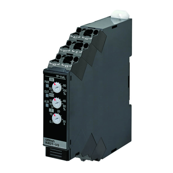
Single-phase Voltage Relay
K8DT-VS
Detect abnormal voltages applies to equipment to
protect against equipment failure.
Use in either overvoltage or undervoltage mode.
• Monitor AC or DC currents with one Relay.
• Settings for the operating value, hysteresis, and operating time.
• Width of 17.5 mm to reduce space required in panels.
• Push-In Plus Terminal that reduce wiring work.
The use of cage clamps enables wiring with bare stranded wires.
Double-insertion holes for crossover wiring (all terminals).
• UL listed for easy shipping to North America.
• Models added with transistor outputs for superior contact reliability.
Refer to Safety Precautions on page 9.
Refer to page 8 for commonly asked questions.
Ordering Information
Single-phase Voltage Relay
Power supply
Setting range
1 to 10 V AC/DC
3 to 30 V AC/DC
15 to 150 V AC/DC
100 to 240 VAC
20 to 200 V AC/DC
30 to 300 V AC/DC
60 to 600 V AC/DC
100 to 240 VAC
Optional Cover
Front Cover
Appearance
Model
Y92A-D1A
Output
voltage
Relay: SPDT contact output
24 VAC/DC
Transistor
Relay: SPDT contact output
Transistor
Relay: SPDT contact output
24 VAC/DC
Transistor
Relay: SPDT contact output
Transistor
For the most recent information on models
that have been certified for safety
standards, refer to your OMRON website.
Model
K8DT-VS2CD
K8DT-VS2TD
K8DT-VS2CA
K8DT-VS2TA
K8DT-VS3CD
K8DT-VS3TD
K8DT-VS3CA
K8DT-VS3TA
1
Advertisement
Table of Contents


Need help?
Do you have a question about the K8DT-VS Series and is the answer not in the manual?
Questions and answers