Table of Contents
Advertisement
Quick Links
New Product
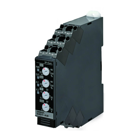
Single-phase Overcurrent/Undercurrent Relay
K8DT-AW
Detect errors in motors and other equipment
through current changes.
Monitor for overcurrents and undercurrents
simultaneously with one Relay.
• Monitor AC or DC currents with one Relay.
• Use with commercially available CTs (CT secondary side: 0 to 1 A or 0 to 5 A).
• Width of 17.5 mm to reduce space required in panels.
• Push-In Plus Technology that reduce wiring work.
Double-insertion holes for crossover wiring (all terminals).
• UL listed for easy shipping to North America.
• Models added with transistor outputs for superior contact reliability.
• RoHS compliant.
Refer to Safety Precautions on page 10.
Refer to page 9 for commonly asked questions.
Ordering Information
Single-phase Overcurrent/Undercurrent Relay
Setting range
2 to 20 mA AC/DC
10 to 100 mA AC/DC
50 to 500 mA AC/DC
0.1 to 1 A AC/DC
0.5 to 5 A AC/DC
10 to 100 A AC *
20 to 200 A AC *
* The K8DT-AW3@@ is designed to be used in combination with an OMRON K8AC-CT200L Current Transformer (CT). (Direct input is not possible.)
OMRON CT
Applicable
Appearance
Input range
10 to 100 A AC,
K8DT-AW3
20 to 200 A AC
Options (Order Separately)
Front Cover
Appearance
Model
Y92A-D1A
Power supply voltage
24 VAC/DC
100 to 240 VAC
24 VAC/DC
100 to 240 VAC
24 VAC/DC
100 to 240 VAC
Model
Relay
K8AC-CT200L
Output
Relay: SPDT contact output
Transistor: Open collector
Relay: SPDT contact output
Transistor: Open collector
Relay: SPDT contact output
Transistor: Open collector
Relay: SPDT contact output
Transistor: Open collector
Relay: SPDT contact output
Transistor: Open collector
Relay: SPDT contact output
Transistor: Open collector
Commercially Available CTs *
CT current on
Appearance
secondary side
0 to 1 A AC,
0 to 5 A AC
* If you use a commercially available CT, do not exceed the overload
capacity of the K8DT-AW2.
For the most recent information on models
that have been certified for safety
standards, refer to your OMRON website.
Model
K8DT-AW1CD
K8DT-AW1TD
K8DT-AW1CA
K8DT-AW1TA
K8DT-AW2CD
K8DT-AW2TD
K8DT-AW2CA
K8DT-AW2TA
K8DT-AW3CD
K8DT-AW3TD
K8DT-AW3CA
K8DT-AW3TA
Applicable Relay
K8DT-AW2
1
Advertisement
Table of Contents

Related Manuals for Omron K8DT-AW Series


Summary of Contents for Omron K8DT-AW Series
- Page 1 K8DT-AW3CA 100 to 240 VAC Transistor: Open collector K8DT-AW3TA * The K8DT-AW3@@ is designed to be used in combination with an OMRON K8AC-CT200L Current Transformer (CT). (Direct input is not possible.) OMRON CT Commercially Available CTs * Applicable CT current on...
- Page 2 1 s at 600% * CT capacity on primary side. *1. The range is selected using connected terminals. *2. The K8DT-AW3 is designed to be used in combination with an OMRON K8AC-CT200L Current Transformer (CT). (Direct input is not possible.)
-
Page 3: Specifications
K8DT-AW3: Continuous input at 120%, 30 s at Overload capacity K8DT-AW2: 0.1 to 1 A AC/DC (Compatible with Operating value setting 200%, and 1 s at 600% with an OMRON CT commercially available CTs.) range (AL1, AL2) (K8AC-CT200L). 0.5 to 5 A AC/DC (Compatible with Note: CT capacity on primary side. -
Page 4: Wiring Example
3. For the current input, you can input only from the C terminal and one other terminal. 4. Refer to Setting Ranges and Wiring Connections on the I1, I2, and I3 current input terminals. 5. The K8DT-AW3 is designed to be used in combination with the OMRON K8AC-CT200L Current Transformer (CT). Wiring Example... -
Page 5: Timing Charts
K8DT-AW Timing Charts Overcurrent and Undercurrent Operation Diagram Undercurrent and Undercurrent Operation Diagram DIP switch settings: SW3 ON and SW4 ON, or DIP switch settings: SW3 OFF and SW4 ON. SW3 OFF and SW4 OFF Power supply voltage Power Hysteresis: Fixed at 5% supply voltage Input Undercurrent... -
Page 6: Dip Switch Settings
K8DT-AW3 For the K8DT-AW3, the I1 terminal is not used. For the K8DT-AW2, the I3 terminal is not used. If using the OMRON K8AC-CT200L CT, connect to terminals k and l on the K8AC-CT200L. Power supply (Terminals kt and lt are not used.) -
Page 7: Setting Method
K8DT-AW Setting Method Setting Current The current knobs (AL1, AL2) are used to set the current. The current can be set to 10% to 100% of the maximum setting range. Turn the knob while there is an input to the input terminals until the alarm indicator flashes (when the set value and the input have reached the same level.) Use this as a guide to set the current. - Page 8 34.5 81.5 33.5 30 dia. 14.5 14.5 Note: The OMRON Current Transformer (CT) is designed to be used with the K8DT-AW3. Use terminals k and l for connections. (Terminals kt and lt are not used.) Options (Order Separately) Front Cover Y92A-D1A 52.7...
-
Page 9: Questions And Answers
K8DT-AW Questions and Answers Checking Operation Can a motor with a rated current of 5 A be moni- tored using the K8DT? Overcurrents Are there any application precautions? Gradually increase the input from 80% of the set value. The input will equal the operating value when the input The K8DT-AW1 and K8DT-AW2 cannot be used with motor exceeds the set value and the alarm indicator starts flashing. -
Page 10: Safety Precautions
K8DT-AW Safety Precautions Be sure to read the precautions for all models in the website at the following URL: http://www.ia.omron.com/. Warning Indications !CAUTION Indicates a potentially hazardous situation which, if not avoided, may result CAUTION in minor or moderate injury or in property Doing so may occasionally result in minor injury due damage. -
Page 11: Precautions For Safe Use
K8DT-AW 30.To prevent wire materials from smoking or igniting, use the wiring Precautions for Safe Use materials given in the following table. 1. Do not use or store the product in the following locations. Stripping length • Locations subject to water, or oil Recommended wire Without With Ferrules... - Page 12 K8DT-AW Screw Mounting Connecting Stranded Wires 1. Pull out the two hooks on the back of the Relay to the outside until Use the following procedure to connect the wires to the terminal block. you hear them click in place. 1.
- Page 13 The following table shows manufacturers and models as of 2015/Dec. Side Front Not isolated 2.5 mm dia. Reinforced insulation (Double insulation) 0.4 mm 2.5 mm Model Manufacturer XW4Z-00B Omron ESD0.40X2.5 Wera SZF 0.4X2.5 Phoenix Contact 0.4X2.5X75 302 Wiha AEF.2.5X75 Facom 210-719 Wago SDI 0.4X2.5X75...
- Page 14 MEMO...
-
Page 15: Terms And Conditions Agreement
Data presented in Omron Company websites, catalogs and other materials is provided as a guide for the user in determining suitability and does not constitute a warranty. It may represent the result of Omron’s test conditions, and the user must correlate it to actual application requirements. - Page 16 The Netherlands Hoffman Estates, IL 60169 U.S.A. Tel: (31)2356-81-300/Fax: (31)2356-81-388 Tel: (1) 847-843-7900/Fax: (1) 847-843-7787 © OMRON Corporation 2016 All Rights Reserved. OMRON (CHINA) CO., LTD. OMRON ASIA PACIFIC PTE. LTD. In the interest of product improvement, Room 2211, Bank of China Tower, No.
Need help?
Do you have a question about the K8DT-AW Series and is the answer not in the manual?
Questions and answers