Table of Contents
Advertisement
Quick Links
Advertisement
Table of Contents

Related Manuals for PLEN Project PLEN:bit

Summary of Contents for PLEN Project PLEN:bit
- Page 1 PLEN:bit Assembly Manual PLEN Project Company 2019/9/25 1 / 53...
-
Page 2: Table Of Contents
12. Chest assembly....46 5. Motion check 1. Let's walk the PLEN:bit!..51 2. How to adjust ServoMotor position 6. -
Page 3: Cautions On Assembly
PLEN-Basic https://makecode.microbit.org/_4e7MEqgEHaw5 PLEN:bit Extensions https://makecode.microbit.org/_0960M8DsVKgc When assembling the servo motors, the initial rotational position of the gear on the motors is important. The assembly instructions includes initial positioning for the motors. Please ensure all motors are properly set. -
Page 4: Common Parts
2. Contents list Contents list 2.1 Common Parts 1. micro:bit 2. Battery 3. Control Board 4. Switch Board set (switch board PCB, , screw x2) 5. Servo Motors x8 6. Head Board Cable 7. Power Cable 8. USB Cable 9. Head Parts(top, bottom) 10. -
Page 5: Special Kit
23. Sound Sensor 24. Label Sticker 25. head board 26. Connector tool 2.2 special kit 1. BLE ver. head board 2. IR sensor 3. PIR sensor 5 / 53... -
Page 6: About The Angle Of Servo Horn
3. About the Servo motor 3.1 Connector orientation 1. There is a direction in the connector of the servo motor. Make sure that the white cable is on the inside. Connector orientation 3.2 About the angle of Servo horn 1. Body balance is important for biped robots. but, since servomotors have individual differences in rotation angle, it is necessary to absorb the individual differences by the servo horn attached to this. - Page 7 servo horn fix image 7 / 53...
-
Page 8: Assembly 1. Preparation
4. Assembly 4.1 Preparation Necessary items 1. Servo Motors x8 2. Label stickers or Circular Stickers 3. Pen Necessary items Procedure Fix the servo number stickers to each Servo motor cable.Write the numbers 0-7 on eight stickers and place them Attach the sticker in a half-folded form to the servo motor cable. Sticker placement 8 / 53... -
Page 9: Switch Board Assembly
4.2 Switch board assembly Necessary items 1. switch board set (switch board PCB, switch board holder, screw x2) Necessary items 9 / 53... - Page 10 Procedure 1. Align the circuit board and plastic part 2. Screw in the circuit board using the two screws at the corners 10 / 53...
-
Page 11: Circuit Board And Battery Wiring
4.3 Circuit board and battery wiring Necessary items 1. back part 2. switch board 3. battery 4. control board 5. micro:bit 6. power cable Necessary items 11 / 53... - Page 12 Procedure 1. Connect the power cable to the switch board 2. Insert the switch board into the back plastic part with the switch and connector going through the appropriate holes as shown in the picture. 12 / 53...
- Page 13 3. Connect the battery to the switch board following the below reference picture. 4. Connect the control board and switch using the power cable. The connectors are different so please ensure the correct connector slides smoothly into the pins. ※ It is necessary to remove the power cable at the time of "Control board wiring"...
- Page 14 connector tool use example 5. Plug in the micro:bit to the control board. 14 / 53...
- Page 15 6. complete set of board assembly is seen below 15 / 53...
-
Page 16: Servo Motor Set-Up
4.4 Servo motor set-up Necessary items 1. Servo motors ×4 (numbers 0,1,4, and 5) 2. Servo bracket Necessary items 16 / 53... - Page 17 Procedure 1. Orient the servo bracket such that the long back is horizontal and towards the back when inserting the servo motors. The side of the bracket with this long bar in the middle is the "back" of the part and concordantly the back of the robot.
- Page 18 3. Again, be careful not to have the cable of servo motor #1 pinched between the motor casing and plastic parts when assembling. 4. Insert servo motor #5 following the same procedure as #1 in the last available position in the bracket. Ensure all servo motor cables are coming out the "front"...
-
Page 19: Assembling The Thighs
4.5 Assembling the Thighs Necessary items 1. The previously assembled servo bracket with servo motors. 2. The previously assembled control board\ battery\ switch board 3. Thigh plastic parts ×2 4. Servo horn ×2 5. Screws ×2 Necessary items 19 / 53... - Page 20 Procedure 1. Ensure the switch board switch is in the off position. Connect servo motors #1 and #5 to the control board pins as shown. The servo motor pins numbering is given in the Appendix 5.2 picture. When connect the motors into the pins, ensure that the black (ground) cable is towards the outside of the control board.
- Page 21 3. Attach the servo horn plastic parts to servo motors #1 and #5 as shown in the photo. Ensure the axis of the + on the horn is aligned with the edges of the servo motors. 4. Orient the servo bracket such that the bar across the center of the bracket is horizontal and at the back of the assembly.
- Page 22 5. Fix the thigh parts to the horn with the screws. 6. After fully screwing in each of the thigh screws, remove the servo cables from the control board. 22 / 53...
-
Page 23: Attaching Leg Parts
4.6 Attaching leg parts Necessary items 1. body sets 2. circuit sets 3. servo×2 (3,7番) 4. legs×2 5. servo horn×2 Necessary items 23 / 53... - Page 24 Procedure 1. Insert servo motors numbers 3 and 7 into the thigh parts as shown. The gears of the servo motors will be pointing towards the "back" of the robot. 2. Connect the servo cables for motors 3 and 7 into the control board. Servo motor number 3 is to be placed as the robot's left leg.
- Page 25 3. The servo motors should rotate automatically to their initial position. 4. Similar to servo motors #1 and #5, attach the servo horns to each servo motor such that the axis of the + on the horn is aligned with the edges of the servo motors as closely as possible.
- Page 26 5. Attach the feet plastic parts while paying attention to ensure the wider side of the feet are towards the outside of the robot. Insert the + side of the foot into the servo horn and then insert the opposite side of the foot into the bump on the front side of the thigh.
-
Page 27: Shoulder Parts Assembly
4.7 Shoulder parts assembly Necessary items 1. body sets 2. circuit sets 3. shoulder×2 4. screw×2 Necessary items 27 / 53... - Page 28 Procedure 1. Connect servo motors #0 and 4 from the servo bracket into their respective pins on the control board and turn the power switch on. 2. The servo motors should rotate automatically to their initial position. 28 / 53...
- Page 29 3. Insert the shoulder parts into servo motors 0 and 4 such that the flat edges are aligned with the servo motor as closely as possible. The wider side of the shoulder parts with the + cut should be towards the back of the robot. Screw in the plastic shoulder part into the servo motor.
- Page 30 5. Unplug the servo motors from the control board and turn the power switch off. 30 / 53...
-
Page 31: Arm Parts Assembly
4.8 Arm parts assembly Necessary items 1. body sets 2. circuit sets 3. arm×2 4. servo×2 (2,6番) 5. servo horn×2 Necessary items 31 / 53... - Page 32 Procedure 1. Place the servo motors #2 and 6 into the plastic arm parts such that motor #2 is the robot's left arm. 2. Directly connect servo motors #2 and 6 into their respective pins on the control board and turn the power switch on. 32 / 53...
- Page 33 3. The servo motors should rotate automatically to their initial position. 4. Attach the servo horns to each servo motor such that the axis of the + on the horn is aligned with the edges of the servo motors as closely as possible.
- Page 34 5. Insert the left and right arms into the shoulder pieces lining up the servo horn with the cut + shape on each shoulder. *Ensure the arms are inserted pointing down. 6. After fixing the arms to the shoulder parts, unplug the servo motors from the control board and turn the power switch off.
-
Page 35: Servo Xer Attachment
4.9 Servo fixer attachment Necessary items 1. Body assembly set 2. Servo fixer part Necessary items 35 / 53... - Page 36 Procedure 1. Pass the cables of the eight servo motors through the servo bracket and through front as shown. The cables of motors #3 and 7 are passed through the lower hole of the bracket, and left there for later. 36 / 53...
- Page 37 2. Servo motors #1 and 5 are passed between the opening in the servo fixer, while the remaining cables are temporarily wrapped up around the top ofthe body to keep them out of the way. 3. Attach the servo fixer part so as to not catch and pinch any of the other servo motor cables.
-
Page 38: Control Board Wiring
4.10 Control board wiring Necessary items 1. Battery assembly 2. Control board assembly Necessary items 38 / 53... - Page 39 Procedure 1. Remove the micro:bit and the power cable from the control board. Pass the power cable along with the servo motor cables from the back side through the front hole in the body and reconnect the power cable to the control board again. 2.
- Page 40 3. Connect all servo motor cables following the appropriate order with servo motor number matching pin number. 40 / 53...
-
Page 41: Head Part Assembly
4.11 Head part assembly Necessary items 1. body sets 2. head parts(top, bottom) 3. head board 4. head board cable Necessary items 41 / 53... - Page 42 Procedure 1. Take apart the top and bottom plastic parts of the head 2. Connect the final head-board control cable to the head-board 42 / 53...
- Page 43 3. Unscrew the nuts on each LED down about 3mm. 4. Pass the head-board cable through the hole in the bottom side of the head plastic part. 43 / 53...
- Page 44 5. Bend the LED legs 90 degrees such that the head-board is rotated up, and insert both LEDs into the semi-circular grooves in the bottom plastic heat part such that the nuts on each LED are on the inside of the head. 6.
- Page 45 7. Insert the head-board cable through the top hole in the servo bracket and pass through the front side of the body. Insert the assembled head into the same hole to fix the head to the servo bracket. 8. Connect the head-board cable into the control board. 45 / 53...
-
Page 46: Chest Assembly
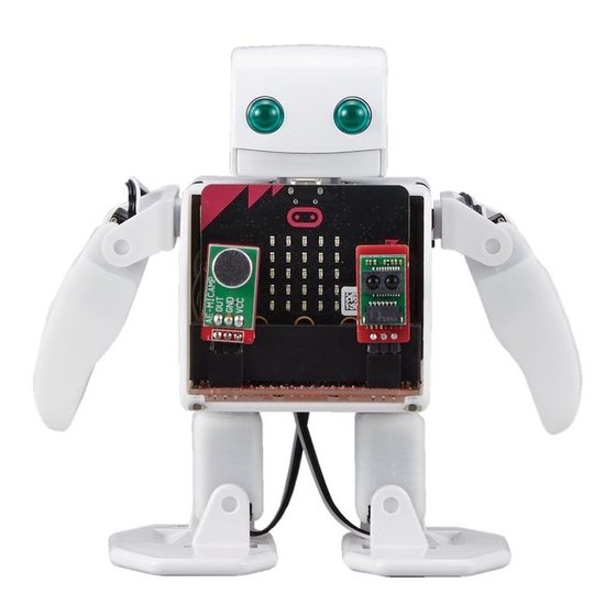
4.12 Chest assembly Necessary items 1. body sets 2. chest 3. micro:bit 4. sound sensor・distance sensor 5. screw×2 Necessary items 46 / 53... - Page 47 Procedure 1. First slide the control board into the chest part from the front oriented as shown in the photo. 2. Attach the control board and chest assembly to the servo bracket body. 47 / 53...
- Page 48 3. Screw the control board into the chest through the two screw holes in the corners of the control board. 4. Insert the micro:bit. 48 / 53...
- Page 49 5. Switch the robot on and confirm if all servo motors have rotated and initialized. 6. Press the micro:bit A and B buttons to check that the limbs work. 49 / 53...
- Page 50 7. Plug the sound sensor and the distance sensor into the pin terminals on the front of the control board on PLEN:bit. 50 / 53...
-
Page 51: Motion Check
3. if can't walk PLEN:bit... Use this ->https://makecode.microbit.org/_Veh6c5AVMawp 4. Plug in the USB cable into PLEN:bit and your computer. A new drive will appear in your file explorer. 5. When you download the files they may be downloaded directly to your computer as a .hex file. -
Page 52: How To Charge Battery
6. How to charge battery 1. Connect PLEN:bit ( back Switch Board ) and PC ( or USB charger ) with cable. 2. Charging : LED ON 3. Full charge : LED OFF 7. How to BLE ver. head board 1. -
Page 53: Appendix
8. Appendix 8.1 PLEN:bit servo numbering 8.2 Control board terminal labelling PLEN:bit Support If you have any questions, please contact one of the following PLEN:bit Slack community : http://u0u0.net/YJzp PLEN Support : https://plen.jp/wp/contact/ 53 / 53...
Need help?
Do you have a question about the PLEN:bit and is the answer not in the manual?
Questions and answers