Advertisement
Table of Contents
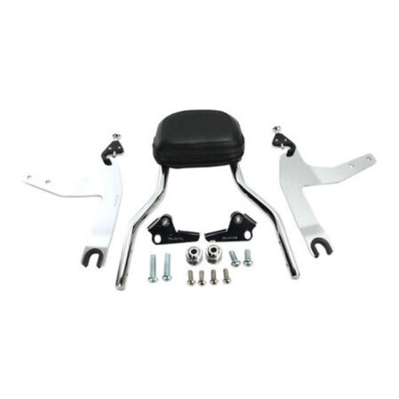
Items Supplied >
1 - Sissy Bar w/ Pad and Insert
2 - Mount Brackets (Left/Right)
2 - Detachable Side Plates (Left/Right)
2 - Front Mounting Bushings
2 - 3/8"-16 x 1-3/4" Buttonhead Bolts
2 - 3/8"-16 x 1" Buttonhead Bolts
4 - M8 x 20mm Buttonhead Bolts
Instruction Manual >
Read all instructions carefully before installing your new Cobra
Remove the front bolt from the right side fender rail and discard. NOTE: Remove one side only so the
1.
fender does not fall resulting in possible scratches or damage to the fender or paint. See FIGURE 1.
Install the front mounting bushing into the front hole using the supplied 3/8"-16 x 1-3/4" long
2.
buttonhead bolt and tighten bolt securely. See FIGURE 2.
Remove the rear most fender rail bolt and discard. See FIGURE 1.
3.
Install the right rear mount bracket into the rear hole using the supplied 3/8"-16 x 1" long buttonhead
4.
bolt and tighten bolt securely. See FIGURE 2.
REMOVE
* Cobra
recommends you always wear a helmet while r iding. Please never operate your motorcycle while under
®
the influence of alcohol and/or drugs. Enjoy the new look of your motorcycle and please ride safely.
DOCUMENT NO. 0017
REV. B
04/17
23801 E. La Palma Ave., Yorba Linda, Ca 92887 Ph. 714.692.8180 Fax. 714.692.5016
®
FIGURE 1
CONTINUED ON PAGE 2
Application(s) >
HARLEY:
FLSTF FATBOY
FXST STANDARD
FXSTS SPRINGER
FXSTB NIGHT TRAIN
602-2002/602-2002B
www.cobrausa-hd.com
07-17
06-09
06-09
06-09
Page 1 of 3
product!
®
REMOVE
®
Advertisement
Table of Contents

Related Manuals for Cobra 602-2002


Summary of Contents for Cobra 602-2002
- Page 1 4 - M8 x 20mm Buttonhead Bolts Instruction Manual > Page 1 of 3 602-2002/602-2002B Read all instructions carefully before installing your new Cobra product! ® Remove the front bolt from the right side fender rail and discard. NOTE: Remove one side only so the fender does not fall resulting in possible scratches or damage to the fender or paint.
- Page 2 23801 E. La Palma Ave., Yorba Linda, Ca 92887 Ph. 714.692.8180 Fax. 714.692.5016 ® www.cobrausa-hd.com Instruction Manual > Page 2 of 3 602-2002/602-2002B RIGHT SIDE FRONT MOUNT BRACKET MOUNTING BUSHING FIGURE 2 Repeat Steps 1-4 on the left side. Install the supplied side plates on to the sissy bar with the four M8 X 20mm button head bolts. Make sure the u-shaped grommets are facing the same direction as the sissy bar pad and the part numbers are facing inward.
- Page 3 23801 E. La Palma Ave., Yorba Linda, Ca 92887 Ph. 714.692.8180 Fax. 714.692.5016 ® www.cobrausa-hd.com Instruction Manual > Page 3 of 3 602-2002/602-2002B DETACHABLE LATCH PIN DETACHABLE LATCH KNOB REAR MOUNTING FRONT MOUNTING BUSHING BUSHING FIGURE 4 Pull backward on both detachable latch knobs and then push downward on the backrest to allow the backrest to sit completely on the rear mounting bushings.
Need help?
Do you have a question about the 602-2002 and is the answer not in the manual?
Questions and answers