
Related Manuals for Scientifica MMBP


Summary of Contents for Scientifica MMBP
- Page 1 Motorised Moveable Base Plate (MMBP) Setup and Operation Manual Revision 2.0 Manual Part No.: S-MMBP-MANUAL...
- Page 2 © Scientifica Ltd 1A Kingfisher Court, Brambleside, Bellbrook Industrial Estate, Uckfield, TN22 1QQ, United Kingdom Tel +44 (0) 1825 749 933 Fax +44 (0) 1825 749 934 info@scientifica.uk.com...
-
Page 3: Table Of Contents
Contents Note: This manual describes the features, functions and operation of the MMBP mounting system. Before use, please carefully read this manual, directions for all accessories, all precautionary information and specifications. 1.0 Product Introduction ..............1 1.1 Handling Scientifica equipment – precautions ......1 1.2 The Scientifica Motorised Moveable Base Plate (MMBP) .... -
Page 5: Product Introduction
This is in contrast to setups where a microscope is translated via a moving stage. The MMBP therefore enables the user to translate a sample in combination with imaging techniques that restrict the movement of the microscope frame. -
Page 6: Product Walkthrough
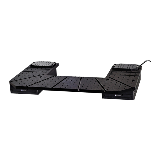
1.2.2 Product Walkthrough Figure A: Motorised Moveable Base Plate, with key components indicated Slave stage Motorised stage (indicated by flying leads) Top plate Multiple versions available for compatibility with different upright microscope. See section 7 for dimensions. These may be supplied with either metric or imperial tapped holes. Post and Platform Sample Chamber mount Sample chamber platform. -
Page 7: Packing List
Scientifica Ltd. Please retain the packaging for storage or future transportation of the system. 2.1 Standard items 1 x MMBP top plate (See Figure A for image) 2 x Protective rubber membranes 1 x Screw kit 1 x Hex key set... - Page 8 1 x User interface cable 1 x Breakout box lead (15-way D-type to RJ45) (25-way D-type) 1 x 1U rack mounted 1 x USB lead controller (A-type to B-type) Post and Platform Bath Platform mount components: 1 x Stainless Steel Post 1 x Screw Down mounting base (350, 140 and 90 mm variants...
-
Page 9: Optional Items
2.2 Optional items User Interfaces – one of the following supplied: Joystick Control Cube Post and Platform manipulator mounts Patch Pad (typically used to mount MicroStar manipulators on the MMBP) PP-3400-00 Alternative mounting options In-vivo sample plate S-PP-3065-00 2.0 Packing List... -
Page 10: Initial Setup
3.2 Fitting the post and platform sample plate to the top plate In order to mount your sample on the MMBP, a Post and Platform system is supplied. For ease of platform positioning you may prefer to fit the post and platform sample plate holder to the MMBP top plate first. -
Page 11: Securing The Post Onto The Mmbp
Place the post into the required position on the top surface of the MMBP. Dependent on the tapped surface of the MMBP, use M6 or ¼-20 screws through the four mounting holes in the post base to attach it onto the surface of the MMBP. -
Page 12: Using The Sample Plate Platform
M3 tapped holes For users wishing to use the Scientifica Slice Recording Chamber kit, the ferro-magnetic outer ring is held in place with eccentric washers using the holes marked C in the above diagram. The sample chamber is then fitted via magnets inside this ring. -
Page 13: Operating The Post And Platform
'home' position to swing out from and return to. When mounted on the MMBP, an ideal 'home' position would centre the chamber in the light path of the microscope. The user can then swing the sample away from the experiment area for convenient access. - Page 14 Figure C: Post and Platform locking collar 2. Loosen the platform clamp and rotate it to your ideal 'home position, keeping the screw on the underside of the platform located in the end stop groove of the silver upper ring. 3.
-
Page 15: Building The Mmbp Around Your Microscope
3.3.1 Positioning the MMBP Note: the MMBP has a total travel of 50 mm in both the X and the Y axis – the top plate will therefore need to be positioned carefully to allow full movement and access around the microscope. - Page 16 4. Place the slave stage on the opposite side of your microscope to the motorised stage. Remove the shipping bracket from the inside edge of the slave stage – nearest the microscope. Leave the outside edge shipping bracket in place. 5.
- Page 17 M6x12 screws. Return the stage to its zero position and replace the outer shipping bracket. 12. Two rubber membranes are supplied with the MMBP in order to prevent the ingress of solution into the stages. Place one of these over each of the stages, aligning the holes in the membranes with those on the top surface of the stages.
-
Page 18: Using The Sliding Carriages
3.4 Using the Sliding Carriages As an alternative to mounting devices directly on the tapped surface of the top plate, three carriages are supplied for when finer positioning control is required. These are usually used for mounting micromanipulators, which can be attached directly to the carriage using the bolts supplied. -
Page 19: Electrical Setup Of The Mmbp
5V input or output signal as follows. TTL In – Inputting a 5V pulse will cause the MMBP to move in the same way as pressing the MR key on the control cube. TTL Out – Pressing the MR key on the control cube will output a 5V pulse. -
Page 20: Basic Mmbp Electrical Setup Diagram
3.3.2 Basic MMBP electrical setup diagram Caution: Never connect or disconnect any cables with the 1U Control rack switched on. Figure F: Basic electrical connections schematic 3.0 Initial Setup... -
Page 21: Example System Diagram
3.3.3 Example system diagram The MMBP can be incorporated into Scientifica’s modular electrical system, enabling control consoles to be shared between devices. Figure G: Example system connection schematic 3.0 Initial Setup... -
Page 22: Operation Guide
The purple Scientifica logos will illuminate, indicating the system is powered up. 4.2 Operating the MMBP Movement of the MMBP is achieved using the user interface supplied. Functionality of each user interface type is described as follows: 4.2.1 Using a Control cube Figure H: Control cube user interface Device selection –... - Page 23 The factory default setting for the step size is 0.01 mm. This value can be changed using Linlab control software. M+ - Pressing the M+ button stores the current position of the MMBP in memory. Moving the MMBP and pressing M+ again will store another position.
-
Page 24: Using A Patchpad
Figure I: PatchPad control device Left wheel (X)– Moves the left and right X axis (blue). The push buttons above the wheel to the left and right will move the MMBP in fast mode when pressed. Middle wheel (Y) – Moves the front and back Y axis. The push buttons above the wheel to the left and right will move the MMBP in fast mode when pressed. - Page 25 M+ - Pressing the M+ button stores the current position of the MMBP in memory. Moving the MMBP and pressing M+ again will store another position. Up to 25 memory positions can be stored. MR - Pressing the MR button will recall the first stored memory position.
-
Page 26: Using A Joystick
Figure J: Joystick control device Move the joystick in the direction of travel required. Moving the joystick to the left or right will move the MMBP left or right in the X axis. Moving the joystick to the front or back will move the MMBP forwards or backwards in the Y axis. -
Page 27: Maintenance
5.0 Maintenance WARNING: Do not tamper with any fixings other than those indicated in the manual for mounting purposes. There are no user serviceable parts within the MMBP. 5.1 Cleaning WARNING: Switch off and disconnect the mains supply before cleaning the unit. -
Page 28: Frequently Asked Questions
6.0 Frequently Asked Questions 6.1 No Movement • Check Scientifica logo is illuminated on the front of the rack • Check for correct switch position on side of cube for controlling Manipulator • Check all cables and connectors for damage or loose connections 6.2 Drift... - Page 29 panel). This may lead to expansion of the headstage and subsequent drift. • You should allow half an hour after switching off before re-testing stability • Recording chamber: are there any cables, wires or tubing connected to the chamber? • Such cables could implement an external force causing movement of the chamber.
-
Page 30: Specifications
All top plates have a depth of 15 mm. The stages have a height of 48 mm, giving a total height from anti-vibration surface to mounting surface of 63 mm. Figure K: Top plate for use with the Scientifica SliceScope (1727) 7.0 Specifications... - Page 31 Figure L: Top plate for use with microscopes from Zeiss, Olympus and Nikon (1726) Figure M: Top plate for use with microscopes from Leica (1850) 7.0 Specifications...
-
Page 32: Sample Mounting Options
7.2 Sample mounting options All dimensions in mm Figure N: Standard bath chamber platform Figure O: In vivo long plate - mounting platform Figure P: In vivo short plate –mounting platform 7.0 Specifications... -
Page 33: Warranty, Technical Queries And Returns
8.0 LinLab - Motorized Device Configuration and Control Software The software utility allows the user to change the configuration of the controller to optimise the settings to suit their specific application. The direction of travel can be adjusted along with speed of acceleration, movement etc. - Page 34 8.1.2 Installing the USB Drivers In order to control the PatchStar via the USB connection the relevant drivers must first be installed. When running the system on Windows XP or Windows 2000, the operating system should detect a new USB device on power up or connection.
- Page 35 Once Windows has finished installing the first driver a second device will be detected. Note: The LinKey driver installation is complete at this point please skip to the section Identifying USB port assignment on the next page. Again, select No, not this time. And install from list or a specific location Browse to the same location as before.
- Page 36 8.1.3 USB port assignment In order to communicate using the USB you must know the communications port that Windows has assigned to the USB port. To do this, open Control Panel from the Start Menu, select System, Hardware, Device Manger and then expand Ports (COM & LPT) your USB serial Port will be displayed as below;...
- Page 37 8.2 Running the software Ensure the controller rack is turned on. To initiate; select the LinLab programme icon under the Scientifica Program group from within the Programme Manager. When you run the software you will open a window like the one shown below: 8.0 LinLab - Motorized Device Configuration and Control Software...
- Page 38 8.2.1 Zero Current Position The user can set the current position as a zero reference in all 3 axis (as determined by the linear motion card) by pressing the Zero Current Position button. The position shown is calculated by counting the number of steps each motor moves and is stored within non-volatile memory on the linear motion card.
- Page 39 8.2.4 Home Out, Home In and Step In If a Home Out position has been set, clicking on Home Out button will cause the device to record its current position (as its Home In value) and then move to the Home Out position as defined by the Set Home Out Position function within the Manipulator menu (described below).
- Page 40 If running a single device the following screen allows you to set the correct comms port. 8.3.2 Configure / System Configuration This allows the user to automatically configure individual Scientifica devices from PatchStar manipulators through to microscope platforms through to heaters: This is particularly useful if you have a multicard system.
- Page 41 8.3.3 Manipulator / Set Home Out Position This allows the user to select the current position as the home out position. After selecting this option a message will appear asking if you are sure that you want to do this. Once selected, the current position is stored as the Home Out position.
- Page 42 8.3.5 Manipulator / Step Size After Home In This allows you to move forward in specific sized steps after the Home In function has been executed. The example below shows a 100 µm steps size. This can be set between 0 and 1 mm. If using a manipulator with a virtual axis;...
- Page 43 8.3.7 Manipulator / Reverse X (Y or Z) Rotary Motion This allows you to reverse the effect of the controller movement i.e. If you turn the control clockwise and the stage moves to the right; click on the Reverse X Joystick and the stage will then move in the opposite direction.
- Page 44 8.3.9 Manipulators/ Creeper Use the creeper function to move towards your sample slowly and steadily. Use this menu to set the speed and the distance to be moved. 8.3.10 Manipulators/ PPL Wheel ReMap PPL Wheel re-map allows you to swap round which wheels control the different axes.
- Page 45 8.3.12 View / Show Stored Points Show Stored Points allows the user to drive to positions, store the coordinates of those positions, edit the name of the positions, grade them, if required and then return to the positions. In order to store a point within LinLab, drive the manipulator or microscope stage to the required location and select AddPoint from the stored points form.
- Page 46 Once you are satisfied with the name and grade of the point click OK. The Stored points form will be updated with the input information and the user can continue to add points. To return to a stored point, click on the point’s name. You can filter the stored points by grade by selecting the drop down menu.
- Page 47 8.3.13 Approach The approach function is generally only used with a Scientifica PatchStar manipulator. It allows the user to manually set an approach angle or sense an approach angle (from the rotary sensor within the PatchStar manipulator). Once enabled the X and Z axis will be driven proportionally to create a virtual 4 axis.
- Page 48 Apply or 8.4 Programming linear motion and Heater Cards Scientifica are happy to provide a summary of commands should users wish to control the LinLab cards through their own software.
- Page 49 Command Title Description Report Pos This reports the position for all three Axis separated by tabs. It can also be used to enter new positions. Report Pos As Above Report Pos X This reports the position for the X Axis. It can also be used to enter a new position.
- Page 50 Command Title Description RESET Restart with This restores default values for defaults. speed, current, and position and restarts the controller. Move Set User This sets a multiplier, which will Units X make the controller, move effectively larger steps for each step requested.
- Page 51 Command Title Description Go to the home in This command can only be used if pos. the last action was “OUT”, it will move the axis to the position it was before the “OUT” command was issued less the was set by “OFFSET”...
- Page 52 The MMBP is warranted against defects in material and workmanship for a period of two years after date of delivery. During the warranty period, Scientifica Ltd will repair or, at its option, replace parts which prove defective when the instrument is returned to Scientifica Ltd in the UK or to your local representative.
-
Page 53: Table Of Figures
Figure J: PatchPad control device ............20 Figure K: Joystick control device ............22 Figure L: Top plate for use with the Scientifica SliceScope (1727) ..26 Figure M: Top plate for use with microscopes from Zeiss, Olympus and Nikon (1726) ..................27 Figure N: Top plate for use with microscopes from Leica (1850) .. -
Page 54: About Scientifica
11.0 About Scientifica Scientifica specialises in the manufacture and distribution of innovative, high quality equipment for electrophysiology researchers, based on principles of careful design and solid engineering. By responding to the unique demands placed on the equipment of electrophysiologists and thinking laterally around these challenges,... - Page 55 © Scientifica Ltd 1A Kingfisher Court, Brambleside, Bellbrook Industrial Estate, Uckfield, TN22 1QQ, United Kingdom Tel +44 (0) 1825 749 933 Fax +44 (0) 1825 749 934 info@scientifica.uk.com...
Need help?
Do you have a question about the MMBP and is the answer not in the manual?
Questions and answers