
Related Manuals for Scientifica IVM


Summary of Contents for Scientifica IVM
- Page 1 Triple Axes In Vivo Micromanipulator Setup and Operation Manual Revision 2.0 Manual Part No.: S-IVM-3000-Manual...
- Page 2 © Scientifica Ltd 1A Kingfisher Court, Brambleside, Bellbrook Industrial Estate, Uckfield, TN22 1QQ, United Kingdom Tel +44 (0) 1825 749 933 Fax +44 (0) 1825 749 934 info@scientifica.uk.com...
-
Page 3: Table Of Contents
3.2.4 Axon Dovetail Adapter Plate ..........7 3.3 Electrical setup of the IVM ............7 3.3.1 Control racks ................. 7 3.3.2 Connecting the IVM to the control rack and user interface ..8 3.3.3. IVM electrical setup diagram ..........9 4.0 Operation Guide ................10 4.1 Powering up the system ............. - Page 4 8.3.15 The Joystick / Rotary Speed scaling ........19 8.3.16 Acceleration / Deceleration ..........19 8.3.17 Z Speed Scaling ..............20 8.4 Programming linear motion and Heater Cards ......20 9.0 Warranty, Technical Queries and Returns ......... 24 10.0 About Scientifica ................ 25 2| 1.0 Product Introduction...
-
Page 5: Product Introduction
1.1 Handling Scientifica equipment – precautions This section contains important safety information related to general use of the IVM. The Scientifica IVM is a piece of scientific equipment and as such requires care when handling. • Before use, carefully read the instructions, including all warnings and cautions. -
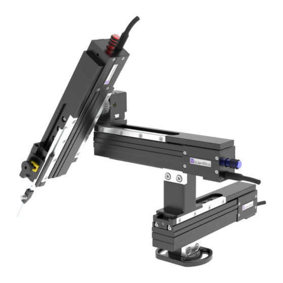
Page 6: Product Walkthrough
6. Z axis motorised body 7. Y axis motorised body 8. X axis motorised body 9. Stoelting bracket (IVM-545-00) 10. IVM Column Assembly - Attaches Y to X (IVM-525-00) 11. IVM Angle Block Assembly - Attaches X to Z (IVM-535-00) 2| 1.0 Product Introduction... - Page 7 Optional brackets: Stoelting Bracket IVM Column Assembly - Attaches (IVM-545-00) Y to X (IVM-535-00) 3 Axis IVM Kopf Mount IVM Angle Block Assembly (IVM-575-00) Attaches X to Z (IVM-525-00) Dove tail probe holder accessory Extended probe holder accessory (PH-1000) (IVM-530-00)
-
Page 8: Packing List
If any of items are missing, contact Scientifica Ltd. Please retain the packaging for storage or future transportation of the system. 2.1 Standard items • Three axes in vivo micromanipulators (IVM) X, Y and Z • 1U controller rack • “PatchPad-One” user interface and connecting cable •... -
Page 9: Initial Setup
1.2.2. 3.2 Building the IVM The IVM 3000 is comprised of three separate single axis manipulators connected by brackets (shown in the figure below). The IVM comes with a range of brackets for mounting, alternative configuration and accessory attachment. -
Page 10: Alternative Ivm Static Base
The IVM static base with Circumferential Mounting Slots (IVM-590-00), provides an alternative mounting solution for the IVM 3000. This bracket allows the IVM to be mounted directly onto a tapped-hole table or stage. Figure B: IVM static base with Circumferential Mounting Slots (IVM-590-00) Use the screws provided with the bracket to secure the bracket to the table/stage in the desired position. -
Page 11: Attaching The Extended Probe Holder Accessory
3.3 Electrical setup of the IVM To operate as a system the IVM will require connecting to a control rack and user interface. There is also an optional connection via USB for PC control using LinLab software. -
Page 12: Connecting The Ivm To The Control Rack And User Interface
If you need to alter your setup, please contact Scientifica. 3.3.2 Connecting the IVM to the control rack and user interface Caution: Never plug or unplug any connections with the controller rack power switched on. -
Page 13: Ivm Electrical Setup Diagram
3.3.3. IVM electrical setup diagram 3.0 Initial Setup... -
Page 14: Operation Guide
The purple Scientifica logos will illuminate, indicating the system is powered up. 4.2 Operating the IVM Movement of the IVM is achieved using the user interface supplied. Functionality of each user interface type is described as follows: 4.2.1 Using a Control Cube Figure A: Control Cube user interface Device selection –... - Page 15 Home In position and the Home Out position. The Home Out position must be set first before Home In can be used. To set Home Out move the IVM to the desired position then press H out for 3 seconds to store the current position. Subsequent pressing of Home Out will cause the IVM to move out to the stored Home Out position until an alternative Home Out position is stored.
-
Page 16: Using A Patchpad
Figure BA: PatchPad control device Left wheel (X)– Moves the IVM X axis(blue). The push buttons above the wheel to the left and right will move the IVM in fast mode when pressed. Middle wheel (Y) – Moves the IVM Y axis (green). The push buttons above the wheel to the left and right will move the IVM in fast mode when pressed. - Page 17 Home In position and the Home Out position. The Home Out position must be set first before Home In can be used. To set Home Out move the IVM to the desired position then press H out for 3 seconds to store the current position. Subsequent pressing of Home Out will cause the IVM to move out to the stored Home Out position until an alternative Home Out position is stored.
-
Page 18: Maintenance
5.0 Maintenance WARNING: Do not tamper with any fixings other than those indicated in the manual for mounting purposes. There are no user serviceable parts within the IVM-3000. 14| 4.0 Operation Guide... -
Page 19: Troubleshooting
5.1 Troubleshooting 5.1.1 No movement • Check Scientifica logo is illuminated on the front of the rack • Check all cables and connectors for damage or loose connections 5.1.2 Drift • Allow the system to warm up • With most electrical components on the rig needing a warm-up period, it is good practice to allow a certain warming-up time after switching on the power of the set-up (up to one hour). - Page 20 • Make sure that all the cables are loose throughout the range of motion and stages. • Is the drift detected with the perfusion running? (test for longer than 10 minutes) • Perfusion solution with a temperature different to the room can lead to thermal expansion of the pipette –...
-
Page 21: Specifications
6.0 Specifications Number of axes Travel 70 mm Step size 20 nm Speed (minimum) 0.1 µm per second (maximum) 4 mm per second Mechanical Resolution <1 µm Load Capacity >0.2 Kg Temperature range Operation 15 to +40ºC Storage 0 to +60ºC 6.0 Specifications... -
Page 22: Dimensional Drawings
7.0 Dimensional Drawings All dimensions are in mm. Side Front Bottom Travel extension: 4| 7.0 Dimensional Drawings... -
Page 23: Linlab - Motorized Device Configuration And Control Software
8.0 LinLab - Motorized Device Configuration and Control Software The software utility allows the user to change the configuration of the controller to optimise the settings to suit their specific application. The direction of travel can be adjusted along with speed of acceleration, movement etc. -
Page 24: Installing The Usb Drivers
8.1.2 Installing the USB Drivers In order to control the PatchStar via the USB connection the relevant drivers must first be installed. When running the system on Windows XP or Windows 2000, the operating system should detect a new USB device on power up or connection. - Page 25 Once Windows has finished installing the first driver a second device will be detected. Note: The LinKey driver installation is complete at this point please skip to the section Identifying USB port assignment on the next page. Again, select No, not this time. And install from list or a specific location Browse to the same location as before.
-
Page 26: Usb Port Assignment
8.1.3 USB port assignment In order to communicate using the USB you must know the communications port that Windows has assigned to the USB port. To do this, open Control Panel from the Start Menu, select System, Hardware, Device Manger and then expand Ports (COM & LPT) your USB serial Port will be displayed as below;... -
Page 27: Running The Software
8.2 Running the software Ensure the controller rack is turned on. To initiate; select the LinLab programme icon under the Scientifica Program group from within the Programme Manager. When you run the software you will open a window like the one shown below: 8.0 LinLab - Motorized Device Configuration and Control Software... -
Page 28: Zero Current Position
8.2.1 Zero Current Position The user can set the current position as a zero reference in all 3 axis (as determined by the linear motion card) by pressing the Zero Current Position button. The position shown is calculated by counting the number of steps each motor moves and is stored within non-volatile memory on the linear motion card. -
Page 29: Home Out, Home In And Step In
8.2.4 Home Out, Home In and Step In If a Home Out position has been set, clicking on Home Out button will cause the device to record its current position (as its Home In value) and then move to the Home Out position as defined by the Set Home Out Position function within the Manipulator menu (described below). -
Page 30: Configure / System Configuration
If running a single device the following screen allows you to set the correct comms port. 8.3.2 Configure / System Configuration This allows the user to automatically configure individual Scientifica devices from Patchstar Manipulators through to Microscope platforms through to Heaters: This is particularly useful if you have a multicard system. -
Page 31: Manipulator / Set Home Out Position
8.3.3 Manipulator / Set Home Out Position This allows the user to select the current position as the home out position. After selecting this option a message will appear asking if you are sure that you want to do this. Once selected, the current position is stored as the Home Out position. -
Page 32: Manipulator / Step Size After Home In
8.3.5 Manipulator / Step Size After Home In This allows you to move forward in specific sized steps after the Home In function has been executed. The example below shows a 100 µm steps size. This can be set between 0 and 1 mm. If using a manipulator with a virtual axis;... -
Page 33: Manipulator / Reverse X (Y Or Z) Rotary Motion
8.3.7 Manipulator / Reverse X (Y or Z) Rotary Motion This allows you to reverse the effect of the controller movement i.e. If you turn the control clockwise and the stage moves to the right; click on the Reverse X Joystick and the stage will then move in the opposite direction. -
Page 34: Manipulators/ Creeper
8.3.9 Manipulators/ Creeper Use the creeper function to move towards your sample slowly and steadily. Use this menu to set the speed and the distance to be moved. 8.3.10 Manipulators/ PPL Wheel ReMap PPL Wheel re-map allows you to swap round which wheels control the different axes. -
Page 35: View / Show Stored Points
8.3.12 View / Show Stored Points Show Stored Points allows the user to drive to positions, store the coordinates of those positions, edit the name of the positions, grade them, if required and then return to the positions. In order to store a point within LinLab, drive the manipulator or microscope stage to the required location and select AddPoint from the stored points form. - Page 36 Once you are satisfied with the name and grade of the point click OK. The Stored points form will be updated with the input information and the user can continue to add points. To return to a stored point, click on the point’s name. You can filter the stored points by grade by selecting the drop down menu.
-
Page 37: Approach
8.3.13 Approach The approach function is generally only used with a Scientifica PatchStar manipulator. It allows the user to manually set an approach angle or sense an approach angle (from the rotary sensor within the PatchStar manipulator). Once enabled the X and Z axis will be driven proportionally to create a virtual 4 axis. -
Page 38: Z Speed Scaling
Apply or 8.4 Programming linear motion and Heater Cards Scientifica are happy to provide a summary of commands should users wish to control the LinLab cards through their own software. - Page 39 Command Title Description Report Pos This reports the position for all three Axis separated by tabs. It can also be used to enter new positions. Report Pos As Above Report Pos X This reports the position for the X Axis. It can also be used to enter a new position.
- Page 40 Command Title Description CURRENT Current This sets the current for the controller in motion and at standby. “CURRENT Motion Standby” the values are in the range 1-255 RESET Restart with This restores default values for defaults. speed, current, and position and restarts the controller.
- Page 41 Command Title Description REGOTO Re-map the GOTO As RESAVE but for the go to button button. Go to the home in This command can only be used if pos. the last action was “OUT”, it will move the axis to the position it was before the “OUT”...
-
Page 42: Warranty, Technical Queries And Returns
9.0 Warranty, Technical Queries and Returns The IVM is warranted against defects in material and workmanship for a period of two years after date of delivery. During the warranty period, Scientifica Ltd will repair or, at its option, replace parts which prove defective when the instrument is returned to Scientifica Ltd in the UK or to your local representative. -
Page 43: About Scientifica
Scientifica Limited is a private limited company registered in England and Wales, registration number 3286415. VAT number: 684 3558 00. Registered office address: Albany House, 14 Shute End, Wokingham, Berks, RG40 1BJ 10.0 About Scientifica... - Page 44 © Scientifica Ltd 1A Kingfisher Court, Brambleside, Bellbrook Industrial Estate, Uckfield, TN22 1QQ, United Kingdom Tel +44 (0) 1825 749 933 Fax +44 (0) 1825 749 934 info@scientifica.uk.com...
Need help?
Do you have a question about the IVM and is the answer not in the manual?
Questions and answers