Advertisement
Quick Links
Advertisement

Subscribe to Our Youtube Channel
Related Manuals for Scientifica SliceMate


Summary of Contents for Scientifica SliceMate
- Page 1 SliceMate Manual...
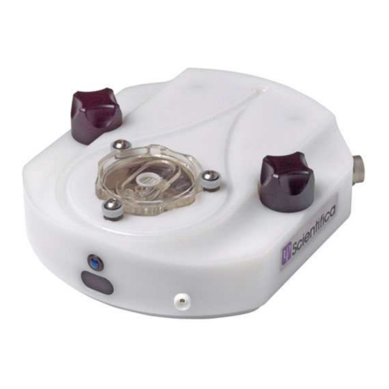
- Page 2 Originally developed as a modular sub-system for use with our unique SliceMaster – multi-channel recording system, the SliceMate is a novel design integrating what would normally be several separate sub-systems into a single line replaceable unit providing a robust, space efficient system.
- Page 3 Stainless Steel ground plane of the SliceMate. The heat exchanger spiral is held in position by a stainless steel spring clip; this ensures the heat exchanger has ideal contact with the Peltier device when the system is assembled.
- Page 4 Digital control and sensor lines The 16 pin electrical connector enables control and communication of the SliceMate to the 19” rack mounted controller. The SliceMate is supplied with a custom power / signal cable that interfaces to the SliceMate thermal control system.
- Page 5 The SliceMate should ideally be sited on a stable vibration isolated table. The base plate accommodates mounting on either 25mm or inch hole spaced table surfaces. For safety during transit, the SliceMate is shipped as one assembly. In order to mount the SliceMate first unscrew the two black Acetyl knobs and lift the SliceMate from its base plate.
- Page 6 The SliceMate bath has a pair of oval suction vents which are connected to the outlet port at the rear of the SliceMate. A typical vacuum/waste setup uses either house vacuum or a suitable pump which is connected to a waste container, which is in turn connected to the outlet port at the rear of the SliceMate.
- Page 7 System Operation Flow control is controlled by triggering the proximity sensor at the front of the SliceMate. This requires a continuous obstruction for more than one second; the system will then switch between on and off. The SliceMate displays proximity sensor (and valve) activation by illuminating or de-illuminating the blue status LED at the front of the module.
-
Page 8: Running An Experiment
Running an Experiment The system must be primed as above. Suspend flow via the proximity sensor Using a pipette, load the brain slice onto the net Reactivate the flow and allow the target temperature to stabilise. Continue with the experiment End Experiment Turn the thermal control off by selecting the station number on the console handset and pressing stop. -
Page 9: Maintenance
Maintenance The SliceMate should be regularly maintained to ensure reliable operation; the frequency of maintenance is dependant on the type of compounds used. It is recommended that all replaceable components listed below be simultaneously exchanged on a regular basis with exception of the brain bath module. - Page 10 The 19” rack controllers must be switched off prior to removing the assembly Once switched; off the 16 way circular connector can be disconnected along with the fluid connections. The SliceMate can now be removed from the SliceMate base. Unscrew the two black Acetyl knobs in an anticlockwise direction and lift the SliceMate clear from the table.
- Page 11 3. To replace the heat exchanger tubing, the spring clip must first be raised. 4. The Stainless Steel lid of the heat exchanger is removed by loosening the 4 hex button head screws and washers using a 2mm Hex wrench. 5.
- Page 12 7. Replace the lid and 4 hex button head screws and washers using the 2mm Hex wrench. 8. Replace the spring clip ensuring the heat exchanger is sitting centrally within it’s housing. Replacing the pinch valve and heat exchanger to bath tubing 1.
- Page 13 4. Take a piece of the silicon pinch valve tubing 80mm long, and carefully push it over the heat exchanger tubing. 5. Now avoiding kinking the heat exchanger tubing, form a comfortable transition from the heat exchanger into the valve jaw. 6.
- Page 14 The brain bath assembly can be removed by first removing the SliceMate from the table as described above. 1. Turn the SliceMate over so that you can gain access to the connectors. And unplug the thermistor and bath connectors along with the inlet and vacuum...
- Page 15 2. Turn the SliceMate back over and unlock the brain bath from the bayonet mechanism and lift the bath free. If replacement silver chloride electrode assemblies are purchased from Scientifica then the old electrode can simply be removed and discarded. The new electrode is then fed from the top side of the bath and then gently pulled from the underside until the surface of the pellet is level with the surface of the bath.
- Page 16 5. Feed connector wire / polythene tube assembly through a new piece of silicon tube of 35mm length. 6. Solder the connector wire to AgCI Electrode (ensure smooth / streamline joint). 7. Ensure polythene sleeve slides freely over solder joint.
- Page 17 8. Push-fit AgCI electrode into the silicon tube (ID 0.063”, OD 0.125”) leaving 0.5mm of AgCI body exposed above tube. 9. Feed assembly through top of brain bath 10. Pull silicon tube until AgCI electrode is level with brain bath surface 11.
- Page 18 Bath Outlet to return heat 1/8”ID platinum cured silicone exchanger return heat exchanger to Outlet 1/8”ID platinum cured silicone Port Bath Earth Ag/Cl pellet E201 33-0003 (Harvard) Bath Earth tube seal Silicone tubing .125”OD .125”ID Thermistor ALA Bead thermistor ALATS-1 Mesh Rings Acetyl 2mm deep ring...
Need help?
Do you have a question about the SliceMate and is the answer not in the manual?
Questions and answers