
Subscribe to Our Youtube Channel
Related Manuals for Sheldon Shel lab SMO28HP-2


Summary of Contents for Sheldon Shel lab SMO28HP-2
- Page 1 HIGH-PERFORMANCE OVENS 220 – 240 Voltage Installation - Operation Manual SMO28HP-2, SMO10HP-2 SMO28HP-2 formerly designated SMO34HP-2...
- Page 2 These ovens require permanent connect wiring (also known as hardwiring) to a power supply. Pictured on the front cover, left to right: SMO28HP-2, SMO10HP-2 The SMO28HP-2 was previously designated SMO34HP-2 Warning: This product contains chemicals, including triglycidyl isocyanurate, known to the State of California to cause cancer as well as birth defects or other reproductive harm.
- Page 3 SLFHP1022-H SLFHP2822-H The Part ID denotes the specific build version of the model. SHEL LAB is a brand of Sheldon Manufacturing, INC, an ISO 9001 certified manufacturer. Safety Certifications These units are CUE listed by TÜV SÜD America as forced air ovens for professional, industrial, or educational use where the preparation or testing of materials is done at an ambient air pressure range of 22.14 –...
-
Page 4: Table Of Contents
TABLE OF CONTENTS INTRODUCTION ..............................5 Read this Manual ..................................5 Safety Considerations and Requirements ........................5 Contacting Assistance ................................6 Manufacturing Warranty ..............................6 Engineering Improvements ..............................6 Reference Sensor Device ..............................7 RECEIVING YOUR UNIT ............................. 9 Inspect the Shipment ................................9 Orientation Images ................................ -
Page 5: Introduction
INTRODUCTION Thank you for purchasing a SHEL LAB oven. We know you have many choices in today’s competitive marketplace when it comes to constant temperature equipment. We appreciate you choosing ours. We stand behind our products and will be here if you need us. EAD THIS ANUAL Failure to follow the guidelines and instructions in this user manual may create a protection... -
Page 6: Contacting Assistance
ONTACTING SSISTANCE Phone hours for Sheldon Customer Support are 6 am – 4:30 pm Pacific Coast Time (west coast of the United States, UTC -8) Monday – Friday. Please have the following information ready when calling or emailing Customer Support: the model, serial, and part numbers and Part ID (see page 12). -
Page 7: Reference Sensor Device
INTRODUCTION EFERENCE ENSOR EVICE Must be purchased separately A reference sensor device is required for calibrating the oven temperature display. Reference devices must meet the following standards: Accurate to at least 0.1°C • Temperature The device should be regularly calibrated, preferably by a third party. Reference Temperature Probes Use a digital device with a wire thermocouple probe that can be introduced into the unit chamber... - Page 8 INTRODUCTION P a g e...
-
Page 9: Receiving Your Unit
RECEIVING YOUR UNIT NSPECT THE HIPMENT When a unit leaves the factory, safe delivery becomes the responsibility of the carrier. • Damage sustained during transit is not covered by the manufacturing defect warranty. • Save the shipping carton until you are certain that the unit and its accessories function •... -
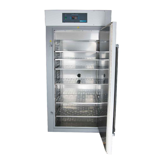
Page 10: Orientation Images
RECEIVING Fuse Holders for Accessory Power Supply Accessory Outlet Outlet 6-20R Feed RIENTATION MAGES (2 amps each) SMO28HP-2 Power Panel (Back) Permanent Connect Wire Braid 6 gauge, 6 inches (150 mm) Access Port – Back of Oven Intake Vent Control Panel Exhaust Vent Temperature Sensor Probes Door... - Page 11 RECEIVING SMO10HP-2 Fuse Holders for Accessory Power Supply Accessory Outlet Outlet 6-20R Feed (2 amps each) Access Port – Back of Oven Power Panel (Back) Permanent Connect Wire Braid 6 gauge, 6 inches (150 mm) Temperature Sensor Probes Intake Vent Control Panel Exhaust Vent Door Gasket...
-
Page 12: Record The Data Plate Information
RECEIVING ECORD THE LATE NFORMATION The data plate contains the unit model number, serial number, part number, and part ID. Customer Support will need this information during any support call. Record it below for future reference. The data plate is located on the back of the oven, next to the power inlet. •... -
Page 13: Installation
INSTALLATION ARDWIRE EQUIREMENT The oven requires permanent connect wiring (commonly known as hardwiring). Wiring to the power source must be performed by a qualified electrical technician. All other Installation steps may be performed by the end-user. NSTALLATION ROCEDURE HECKLIST For installing the unit in a new workspace location. Pre-Installation ... -
Page 14: Required Ambient Conditions
INSTALLATION EQUIRED MBIENT ONDITIONS These units are intended for use indoors, at room temperatures between 15°C and 40°C (59°F and 104°F), at no greater than 80% Relative Humidity (at 25°C / 77°F). Operating outside these conditions may adversely affect the unit temperature performance. When selecting a location to install the unit, consider all environmental conditions that can affect its temperature performance. -
Page 15: Power Source Requirements
INSTALLATION OWER OURCE EQUIREMENTS When selecting a location for the oven, verify that each of the following requirements is satisfied: Power Supply: The power supply must meet the power requirements listed on the unit data plate. These units are intended for 220 – 240 volt, 50/60 Hz applications at the following •... -
Page 16: Power Feed Wiring
INSTALLATION OWER IRING The oven comes provided with an integral 6-inch (150 mm) wire braid consisting of: SMO10HP-2 – two 6-gauge hot wires and a 6-gauge earth ground. • SMO28HP-2 – two 6-gauge hot wires and a 6-gauge earth ground. •... -
Page 17: Leveling
INSTALLATION EVELING Install the 4 leveling feet in the corner holes on the bottom of the oven. The oven must be level and stable for safe operation. Note: To prevent damage when moving the unit, turn all 4 leveling feet so that the leg of each foot sits inside the unit. -
Page 18: Shelving Installation
INSTALLATION HELVING NSTALLATION Airflow: The horizontal airflow in the chamber moves from the small duct holes in the chamber right wall, across the shelf space, and into the large holes in the left wall. To maximize airflow, avoid obstructing the duct holes on either side as much as possible when placing shelves. Spacing: Space the shelves evenly in the oven chamber to ensure the best possible temperature uniformity. -
Page 19: Graphic Symbols
GRAPHIC SYMBOLS The unit is provided with graphic symbols on its exterior. These identify hazards and adjustable components as well as important notes in the user manual. Symbol Definition Consult the user manual Consulter le manuel d'utilisation Indicates adjustable temperature Indique température réglable AC Power Repère le courant alternatif... - Page 20 SYMBOLS 20 | P a g e...
-
Page 21: Control Overview
CONTROL OVERVIEW Control Panel Power Switch The switch illuminates when in the ON ( I ) position. Temperature Controller – Display on Homepage Top Line (Red): Present chamber air temperature Middle Line (Green): The constant temperature setpoint Bottom Line: Flashing “2” indicates active heating While on the homepage, the Up and Down arrow buttons adjust the constant temperature setpoint. - Page 22 CONTROL 22 | P a g e...
-
Page 23: Operation
OPERATION Safe operation of the oven is dependent on the actions and behavior of the oven operators. Operating personnel must read and understand the Operating Precautions in this section prior to operating the oven. The operators must follow these instructions to prevent injuries and to safeguard their health, environment, and the materials being treated in the oven, as well as to prevent damage to the oven. -
Page 24: Theory Of Operations
OPERATION HEORY OF PERATIONS Heating The oven temperature controller stores an end-user-selected constant temperature setpoint. When powered, the oven heats the chamber atmosphere to the setpoint. The controller board is wired to a solid-state temperature probe located in the chamber on the rear wall. When the controller detects that the chamber temperature has dropped below the temperature setpoint, it pulses power to the heating elements. - Page 25 OPERATION Vents: Intake and Exhaust The oven is provided with an intake vent and an exhaust vent. These may be opened or closed using dampener slides located on the vents. The vents are intended to be opened after the heat treatment or bake out phase of an application is complete.
-
Page 26: Put The Oven Into Operation
OPERATION UT THE VEN INTO PERATION Perform the procedures below after the unit has been installed in a new workplace location. These prepare the oven for normal use. Turn on the Oven Place the oven Power Switch in the ON ( I ) position. The controller display will illuminate and default to the •... -
Page 27: Set The High Temperature Limit
OPERATION ET THE EMPERATURE IMIT Note: Test the high limit system once per year for functionality. Set the high temperature limit at least 10°C above the highest temperature the oven will run at during your recipe program or constant-temperature application. See the High Temperature Limit system explanation on page 25. -
Page 28: Setting The Constant Temperature Setpoint
OPERATION ETTING THE ONSTANT EMPERATURE ETPOINT Adjust the Constant Temperature Setpoint on the Homepage Stay 10°C below the high limit • setpoint. Note: Holding down an arrow button will cause the temperature to advance in increments of ten (10). Adjust Release the Arrow buttons after adjusting the Setpoint There may be a brief pause as the oven controller •... -
Page 29: High Temperature Limit Activated
OPERATION EMPERATURE IMIT CTIVATED The High Limit system cuts off heating in the oven whenever the chamber temperature meets or exceeds the Limit setting. Heating remains disabled until the oven end-user clears the Limit cutoff. Indicators When heating is cut off, the oven display flashes two alternating alert screens. Alternating Alert Screens Additionally, an illuminated “4”... -
Page 30: Venting The Exhaust Port
OPERATION ENTING THE XHAUST Optional: The oven does not require venting to operate. However, evacuating exhaust out of the workspace can help prevent elevated temperatures and the buildup of unpleasant odors. Obtain flexible, non-insulated ducting. • Attach the ducting to the lip of the exhaust port on the top, right side of the oven. See the •... -
Page 31: Power Exhaust Blower
OPERATION OWER XHAUST LOWER Note: Exposure to sustained oven chamber temperatures above 80°C will damage the exhaust blower while it is turned off. Leave the oven exhaust vent dampener closed to until it is time to turn on the blower and actively vent the oven chamber. SHEL LAB offers an accessory forced-air power exhaust blower that can be mounted directly on the exhaust vent cover. - Page 32 OPERATION Continued from the previous page Activating the Power Exhaust Blower The exhaust blower can be activated either as part of a heating recipe program or manually from the homepage Options menu while running a constant temperature setpoint. The exhaust blower will significantly impact the oven chamber temperature when on and should be used after completing a heat application.
-
Page 33: Data Port
OPERATION The 9-pin RS485 data port, located on the back of the oven, connects to the oven temperature controller. It is primarily intended for updating the controller software but can be used for data logging and graphical temperature recipe programming. Accessing the controller with a computer requires a 9-pin RS485-to-USB converter cable and driver software. - Page 34 OPERATION 34 | P a g e...
-
Page 35: User Maintenance
USER MAINTENANCE Warning: Disconnect the unit from its power supply prior to maintenance or cleaning of this unit. Avertissement: Avant d'effectuer toute maintenance ou entretien de cet appareil, débrancher le cordon secteur de la source d'alimentation. LEANING AND ISINFECTING Periodic cleaning is required. •... -
Page 36: Door Gaskets And Chamber Integrity
MAINTENANCE Disinfecting Disinfect the oven if algae, mold, bacteria, or other biological contaminants are an issue. For maximum effectiveness, disinfection procedures are typically performed after cleaning. Keep the following points in mind when disinfecting the oven: Turn off and disconnect the unit to safeguard against electrical hazards. •... -
Page 37: Calibrating The Temperature Display
MAINTENANCE ALIBRATING THE EMPERATURE ISPLAY Note: Performing an accurate calibration of the temperature display requires a temperature reference device. Please see the Reference Sensor Devices entry on page 7 for the minimum device requirements. Temperature calibrations match the temperature display to the actual air temperature inside the oven chamber. - Page 38 MAINTENANCE 6. The oven temperature must be stable in order to perform an accurate calibration. The temperature is considered stabilized when the oven chamber has operated with the door closed at your calibration temperature for at least one hour with no fluctuations greater than the specified stability of the oven (see page 51).
- Page 39 MAINTENANCE Calibration continued Unlock the controller. See the Unlocking procedure on page 41. • Note: The temperature controller must be unlocked in order to access the Operations menu and enter a calibration offset. Navigate to the Operations menu after unlocking the controller.
- Page 40 MAINTENANCE Calibration continued Wait for 30 minutes for the oven to stabilize, after the oven has achieved the setpoint with the corrected display value. Failure to wait until the oven is fully stabilized will • result in an inaccurate reading. Compare the reference device reading with the chamber Reference Device display again.
-
Page 41: Unlocking The Temperature Controller
MAINTENANCE NLOCKING THE EMPERATURE ONTROLLER The oven temperature controller is software locked at the factory to ensure the integrity of its configuration file. This safeguards against end-users accidentally altering the oven functionality or safe operating bounds. The controller must be unlocked in order to access the Operations menu and enter calibration offsets. - Page 42 MAINTENANCE Unlocking the Controller Continued Advance to the second security parameter, “LoC.P” a. Push the Advance button once, saving the previous parameter and advancing to the next parameter. Adjust the LoC.P setting from 2 to 3. a. Push the Up arrow button. Advance twice.
- Page 43 MAINTENANCE Unlocking the Controller Continued Change the “SLoC” parameter from 2 to 5. a. Push the Up arrow button. Return to the homepage to access the now unlocked Operations page. a. Push the Reset button twice. Relocking the Controller Always relock the controller after completing a calibration or other Operations menu procedure. To relock controller, repeat the Unlocking procedure, only this time restore all of the •...
-
Page 44: Heating Issues - Diagnostic Questionnaire
MAINTENANCE — D EATING SSUES IAGNOSTIC UESTIONNAIRE If the unit is experiencing heating issues, use this questionnaire to gather information on the unit prior to contacting Customer Support. Gathering and sharing this information aids Customer Support in making timely and accurate remote diagnoses. Additionally, datalogger files, as well as pictures and videos of the unit in its failure mode, are valuable diagnostic resources that can be shared with Customer Support. - Page 45 MAINTENANCE Note: Does the car actually have gas in the tank? Have you physically verified the computer is plugged in? Yes, we are going to ask some very basic questions. Please bear with us. Methodical verifications and the elimination of potential failure causes are often the quickest means of getting a unit back into operation.
- Page 46 MAINTENANCE Required Item: Temperature reference device. A calibrated digital thermometer with wire thermocouple probes. The device must be accurate to at least 0.1°C. Preparing for the Heating Diagnostic Observations The unit must be hardwired to a power source that meets the requirements in the Installation chapter (page 15) and turned on.
- Page 47 MAINTENANCE Heating Diagnostic Questions Record the answers in the log on page 48. etpoint? What is the current temperature setpoint? Chamber Temperature in Red Setpoint in Green hamber Temperature? What temperature is presently showing on the temperature controller display? eference? Optional: What temperature is the reference device presently showing for the chamber? eating Indicator On? Is the heating active indicator on the temperature controller display flashing or otherwise...
- Page 48 MAINTENANCE Heating Diagnostic Data Log Record answers to the Heating Diagnostic questions in this log. These document the unit behavior. Diagnostic Questions Record Answers and Any Notes Here etpoint, present setting: hamber Temperature, present reading: eference Device, present reading: eating Indicator On, Y/N? igh Limit Activated, Y/N? mbient, present temperature:...
-
Page 49: Unit Specifications
UNIT SPECIFICATIONS These ovens are 220 – 240 voltage single phase units. Please refer to the oven data plate for individual electrical specifications. Technical data specified applies to units with standard equipment at an ambient temperature of 25°C and at nominal voltage. The temperatures specified are determined in accordance with factory standard following DIN 12880 respecting the recommended wall clearances of 10% of the height, width, and depth of the inner chamber. -
Page 50: Capacity
SPECIFICATIONS APACITY Model Cubic Feet Liters 10.6 301.0 SMO10HP-2 SMO28HP-2 28.0 792.0 Shelf Capacity by Weight Model Per Shelf Total SMO10HP-2 75.0 lb / 34.0 kg 225.0 lb / 102.0 kg SMO28HP-2 75.0 lb / 34.0 kg 450.0 lb / 204.0 kg ERFORMANCE Ventilation Rates Model... -
Page 51: Temperature Performance
SPECIFICATIONS EMPERATURE ERFORMANCE Range Model Operating Range SMO10HP-2 Ambient +15° to 306°C SMO28HP-2 Ambient +15° to 306°C Uniformity Model @80°C @150°C @306°C SMO10HP-2 ±1.5°C ±2.5°C ±5.5°C ±5.5°C SMO28HP-2 ±1.5°C ±2.5°C Stability Model @80°C @150°C @306°C SMO10HP-2 ±0.2°C ±0.3°C ±0.4°C SMO28HP-2 ±0.2°C ±0.3°C ±0.4°C... -
Page 52: Power
SPECIFICATIONS Temperature Performance Continued Recovery Times from a 30 Second Door Opening Model @ 80°C @ 150°C @ 306°C SMO10HP-2 3 minutes 3 minutes 6 minutes SMO28HP-2 3 minutes 3 minutes 5 minutes Recovery Times from a 60 Second Door Opening Model @ 80°C @ 150°C... -
Page 53: Parts List
PARTS LIST Description Parts Number Description Parts Number Shelf Assembly, 19 x 29”, Adjustable Leveling Feet SMO10HP-2 2700506 995-00007 Door Gasket Fiberglass with clips, 1ft section Shelf Assembly, 23 x 31, SMO10HP-2 (requires 11.5 SMO28HP-2 feet) SMO28HP-2 (requires 17 995-00005 feet) 3450642 Power Exhaust Blower Unit,... - Page 54 P.O. Box 627 Cornelius, OR 97113 support@sheldonmfg.com sheldonmanufacturing.com 1-800-322-4897 (503) 640-3000 FAX: 503 640-1366...
Need help?
Do you have a question about the Shel lab SMO28HP-2 and is the answer not in the manual?
Questions and answers