
Related Manuals for Lincoln Electric COOL ARC 24


Summary of Contents for Lincoln Electric COOL ARC 24
- Page 1 IM3105 03/2020 REV03 ® COOL ARC OPERATOR’S MANUAL ENGLISH Lincoln Electric Bester Sp. z o.o. ul. Jana III Sobieskiego 19A, 58-263 Bielawa, Poland...
-
Page 2: Table Of Contents
12/05 THANKS! For having chosen the QUALITY of the Lincoln Electric products. Please Examine Package and Equipment in case of Damage. Claims for material damaged in shipment must be notified immediately to the dealer. For future reference record in the table below your equipment identification information. Model Name, Code &... -
Page 3: Index
Technical Specifications NAME INDEX COOL ARC ® K14190-1 INPUT Input Voltage U Input Amperes I 1max COOL ARC ® 390 Vdc 0,8 A Frequency EMC Class COOL ARC ® 50/60 Hz PARAMETERS RATING The cooling power of flow 1liter per minute at Maximum pressure rate temperature of 25°C COOL ARC... -
Page 4: Electromagnetic Compatibility (Emc)
If any electromagnetic disturbances are detected the operator must put in place corrective actions to eliminate these disturbances with, if necessary, assistance from Lincoln Electric. Before installing the machine, the operator must check the work area for any devices that may malfunction because of electromagnetic disturbances. -
Page 5: Safety
Failure to follow the instructions in this manual could cause serious personal injury, loss of life, or damage to this equipment. Read and understand the following explanations of the warning symbols. Lincoln Electric is not responsible for damages caused by improper installation, improper care or abnormal operation. - Page 6 CYLINDER MAY EXPLODE IF DAMAGED: Use only compressed gas cylinders containing the correct shielding gas for the process used and properly operating regulators designed for the gas and pressure used. Always keep cylinders in an upright position securely chained to a fixed support. Do not move or transport gas cylinders with the protection cap removed.
-
Page 7: Introduction
Introduction ® ® The COOL ARC 24 is a cooling system designed for use COOL ARC 24 is delivered empty with no coolant in the witch water-cooler torches and guns: system. GTAW torches. Recommended equipment, which can be bought by user, was mentioned in the chapter "Accessories". -
Page 8: Installation And Operator Instructions
Installation and Operator Instructions Read this entire section before installation or operation Input Supply Connection of the machine. The COOL ARC ® 24 must be supplied by a welding power source in accordance with installation procedure WARNING that can be done only by qualified electrician. Installation must be made in accordance with the appropriate ELECTRIC SHOCK can kill. -
Page 9: Controls And Operational Features
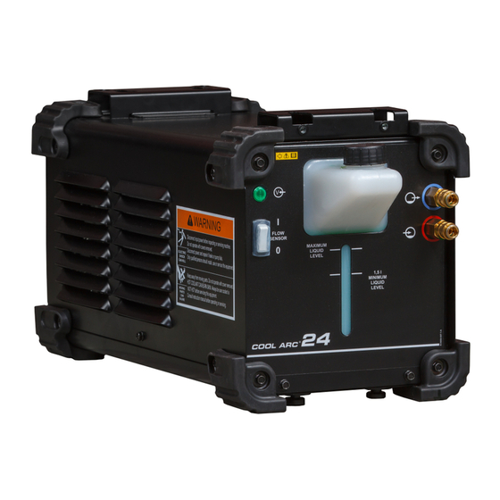
Controls and Operational Features Figure 3 1. Power Indicator Light: This lamp will illuminate when the pump and internal fan are on. The light does not indicate the COOL ARC ® 24 is being supplied by the power source. Figure 4 2. -
Page 10: Circulation Of Coolant In The Cooler
9. Fuse Receptacle: A 2A fuse is present to protect the Filling the reservoir and water lines motor pump. WARNING 10. Removable Strainer. The pump is equipped with a Avoid contact with coolant. Wear waterproof 150um strainer: an external cover is supplied to gloves and protective eye wear. -
Page 11: Connecting The Cooling System Hoses
Connecting the Cooling System Hoses WARNING ® At first using of the COOL ARC 24 reservoir’s nut has to The power source has to be turned off. be removed to avoid generate partial vacuum in cooling Connect the "outlet" hose of torch/gun (colored or system during priming pump. -
Page 12: Transport
For any repair operations, modifications or maintenance, it is recommended to contact the nearest Technical Service Symbols used Center or Lincoln Electric. Repairs and modifications performed by unauthorized service or personnel will Symbol Description cause the manufacturer’s warranty to become null and void. -
Page 13: Pump Inlet Strainer Maintenance
Access the strainer WARNING Do not touch electrically live parts. Disconnect welder and cooler from power. The strainer access panel is located on the back lower left, remove two screws – see Figure 9. WARNING Before the case of machine will be removed, the machine had to be turned off and the power lead had to be disconnected from mains socket. -
Page 14: Troubleshooting
WARNING If for any reason you do not understand the test procedures or are unable to perform the tests/repairs safely, contact the nearest authorized Technical Service Center or Lincoln Electric for technical troubleshooting assistance before you proceed. LOCATE PROBLEM POSSIBLE CAUSE RECOMMENDED COURSE OF ACTION (SYMPTOM). -
Page 15: Customer Assistance Policy
Electric for advice or information about their use of our products. We respond to our customers based on the best information in our possession at that time. Lincoln Electric is not in a position to warrant or guarantee such advice, and assumes no liability, with respect to such information or advice. -
Page 16: Weee
12/05 Part List reading instructions Do not use this part list for a machine if its code number is not listed. Contact the Lincoln Electric Service Department for any code number not listed. Use the illustration of assembly page and the table below to determine where the part is located for your particular code machine. -
Page 17: Accessories
Accessories W000010167 FREEZCOOL (coolant) W000404213 PRESTOTIG 200 AC/DC W000404214 CITOTIG 200 AC/DC K14189-1 ASPECT 200 English English...
Need help?
Do you have a question about the COOL ARC 24 and is the answer not in the manual?
Questions and answers