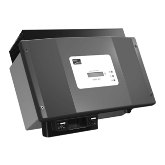
SMA Sunny Boy 2500 Quick Installation Manual
String inverter
Hide thumbs
Also See for Sunny Boy 2500:
- Installation manual (76 pages) ,
- User manual (2 pages) ,
- Installation manual (72 pages)
Advertisement
Available languages
Available languages
Quick Links
Advertisement

Related Manuals for SMA Sunny Boy 2500


Summary of Contents for SMA Sunny Boy 2500
-
Page 2: Sunny Boy 2500
E a rt h Fa u lt S tö ru Kommunikationsmöglichkei- Fa il u ten des Sunny Boy 2500 so- alle einstellbaren Parameter. Technische Daten des Sunny Boy 2500 Eingangsspannungsbereich U PV : 250 V bis 600 V... - Page 3 Voraussetzung für die Montage des Sunny Boy 1. Der Montageuntergrund muss fest sein. Die Montage des Sunny Boy auf Gipskartonplatten o. Ä. kann auf Grund der geringfügigen Vibrationen des Geräts zu Geräuschentwicklung führen. 2. Die Umgebungstemperatur muss zwischen -25 °C und +60 °C liegen.
- Page 4 Konfektionierung des AC-Steckers Druckschraube Druckschraube Je nach Querschnitt des AC-Kabels müssen Sie die Version PG16 Version PG13,5 PG13,5- oder die PG16-Verschraubung benutzen. 1. Drücken Sie den Dichtungsring in den Klemmkorb (nur bei PG13,5). 2. Schieben Sie nun zuerst die Druckschraube mit dem Klemmkorb für PG13,5-...
- Page 5 LEDs auf der Frontplatte LEDs Gehäusedeckel zeigen Betriebszustand des Sunny Boy an. Einzelheiten entnehmen Sie bitte der Technischen Beschreibung des Sunny Boy 2500. Folgende Zeichenerklärung für den Zustand der LEDs: B e t r i S W R 2 5 0 0 Be tri Ph ot O pe...
- Page 6 Please read first The following instructions for installation will help you to commission the Sunny Boy 2500. They do not replace the Sunny Boy 2500 Manual. You will find a complete des- cription of all functions as well information communication equipment...
-
Page 7: Mounting The Sunny Boy
Make sure before mounting the Sunny Boy: 1. The mounting background must be firm. Mounting the Sunny Boy on gypsum plaster board or similar materi- al can result in the production of noise due to the slight vibrations of the inverter. 2. -
Page 8: Commissioning The Sunny Boy
Preparation of the AC plug connector Choose the PG13.5 or PG16 fastening clamp depending on the cross-section of the AC cable. 1. Push the rubber ring into the fastening case (only for PG13.5). 2. Put the cable through the PG 13.5 or 16 cable seal with the fastening case and through the socket tube. -
Page 9: Leds On The Front Panel
LEDs on the front panel The LEDs on the lid display the operating state the Sunny Boy is in. For details please refer to the Sunny Boy 2500 Technical Description. Description of the symbols used in the following section: LED off... - Page 10 F a il u cation du Sunny Boy 2500 ainsi que tous les paramètres ajustables. Données techniques du Sunny Boy 2500 Plage de tension d'entrée, U PV : 250 V à 600 V Portée CA, U CA : 198 V à 251 V AC Courant d'entrée max., I PVmax :...
- Page 11 Conditions préalables pour le montage du Sunny Boy 1. La surface de montage doit être firme. Le montage du Sunny Boy sur des plateaux de carton en plâtre ou des matériaux similaires peut résulter en la production de bruit à cause de vibrations minimes de l'appareil. 2.
- Page 12 Préparation de la fiche CA Raccord PG16 Raccord PG13,5 Selon la coupe transversale du câble CA utiliser le raccord PG 13,5 ou PG 16. 1. Pousser l'anneau obturateur dans le pannier serre (avec PG 13,5 seulement). 2. Pousser d'abord le raccord PG16 ou PG 13,5 (ce der- nier avec le pannier serre) sur le câble.
- Page 13 DELs sur le panneau frontal Les DELs sur le couvercle de la boîte montrent l'état de fonctionn- nement du Sunny Boy. Lire la Description Technique du Sunny Boy 2500 pour obtenir plus de détails. “Operation” = “Opération”, “Earth Fault” = “Contact à la terre”, “Failure”...
- Page 14 Datos Técnicos del Sunny Boy 2500 Área de trabajo CA U CA : 198 V - 251 V CA Rango del voltaje de entrada U PV :...
- Page 15 Criterios para el montaje del Sunny Boy: 1. El fondo del montaje debe ser firme. El montaje del Sunny Boy sobre paneles de cartón yeso o similares puede resultar en la producción de ruido debido a las vibraciones mínimas del aparato. 2.
- Page 16 Preparación del enchufe de CA: Según la sección transversal del cable CA utilizar la junta de rosca PG 13,5 o PG 16. 1. Apretar el anillo de junta en la cesta de borne (sólo en caso de PG 13,5). 2. Primeramente meter la junta de rosca PG 13,5 con la cesta de borne o la junta de rosca PG 16 sobre el ca- ble.
- Page 17 Diodos LED en la placa frontal El usuario puede obtener el estado operativo de los inversores a partir de tres diodos LED. Véase la Descripción Técnica del Sunny Boy 2500 para detalles. “Operation” = “Operación”; “Earth Fault” = “Conexión a tierra” “Failure”...
Need help?
Do you have a question about the Sunny Boy 2500 and is the answer not in the manual?
Questions and answers