Table of Contents
Advertisement
Quick Links
Advertisement
Table of Contents

Related Manuals for Diamond Antenna CP-5HS


Summary of Contents for Diamond Antenna CP-5HS
- Page 2 ●ワンサイド形ラジアル...
- Page 3 ●VSWR表 -100 +100 28-29 -125 +125 -1500 +1500 ●規 格 周波数 / 7,14,21,28〜29,50MHz CP-5HS インピーダンス / 50Ω VSWR / 1.5以下(共振周波数にて) 耐入力 / 200WSSB(7MHz) 400WSSB(14/21MHz) (図−9 ) 500WSSB(28/29/50MHz) FM/CWではSSBの約1/3程度に なります 耐風速 / 45m/sec. 全長 / 3.6m ラジアル長 / 約1.8m 重量 /約3.4Kg 適合マスト径 / 30〜62φ 接栓 / M-J型 形式 / 5バンドグランドプレーン 空中線形式 / 中間部負荷型 (表−A) 2007年11月 第1版発行 2007第一電波工業株式会社...
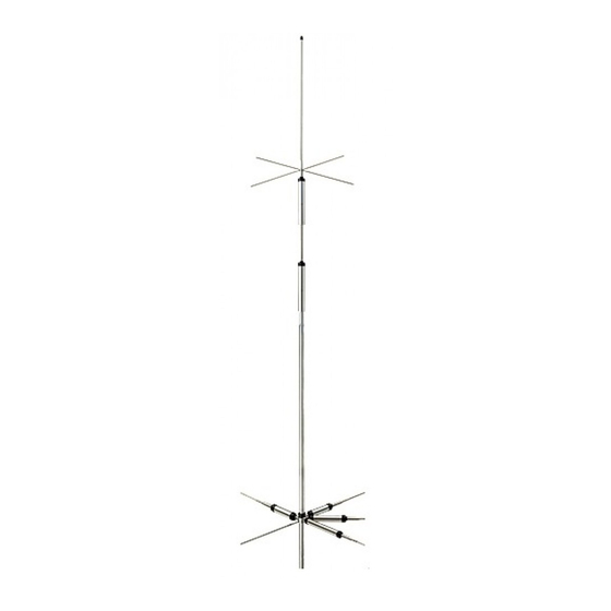
- Page 4 40m,20m,15m,10m and 6m(7/14/21/28-29 and 50MHz) Five-band Vertical Antenna Operation Instructions ・ Description ①The CP-5HS is a five-band vertical ・ Parts Description antenna for HF band. ②Compact, light weighted and very easy to assemble. ③It is completely self-supported and does not need any guy wires. ④Trap radials could be concentrated on Pipe No. 1 φ15 M39006 one direction instead of spreading them around the antenna. This is especially convenient if the antenna is Capacity hat assembly installed on balconyrailing or window M39009 side of condominiums and urban apartments. Internal tooth lock washer M4 Capacity hat M39021 ⑤Since the antenna is direct DC ground fastener ring M39022 Tapping screw M4 x 8 at the feed point, coaxial cable and M39020 transceiver are being protected from the high voltage caused by lighting. Double element trap coil assembly ⑥Center frequencies of the antenna are M39007 adjustable in each band simply by change Screw with radial ...
- Page 5 friends for help installing the antenna. ①Keeping transmitting with high VSWR ③Donʼt drop the antenna, tools and may cause the radio to be damaged. (Fig-3) attachment when installing the antenna Stop transmitting immediately and in the height. Install the antenna before ・ In case of using the metallic stay check the following matters. If it wire, set the wire on the lower assembling it on the ground. doesnʼt solve the problem, please mast bracket set and attach the ask the dealer or Diamond Antenna insulators at within 1m from the 《Antenna location》 mast bracket set in order to Corporation. ①If the CP-5HS is located on the insulate. [Condition: If the antenna doesnʼt seem roof of a house or top of a building, ・ It is possible to remove the radials to receive well or propagate well] you donít use the band for. look around the roof to see if there Check 1: Is the antenna too close to are any obstacles such as an electronic the building wall? If the obstacles are One direction style radial elements wire or TV antenna. The CP-5HS too close to antenna, VSWR is higher has to be located as far away as and the radiation pattern is disturbed. possible from those things to obtain Please install the antenna from the its maximum performance. Installing ...
- Page 6 Frequency range 40, 20, 15, 10, 6m (7, 14, 21, 28-29, 50MHz) Support ①Prepare suitable VSWR meter for Feed point Impedance 50Ω Mast pipe operating frequencies and output VSWR Less than 1.5 RF power. Then connect it as shown Maximum power rating in below. 200W SSB (7MHz) V-bolt CP-5HS (Fig-7) 400W SSB (14/21MHz) 500WSSB(28/29/50MHz) ⑥Place the two radial element holder Maximum RF power rating of from upper end of the support pipe VSWR Tranceiver continuous wave (FM/CW) is about meter and fasten temporary with screwdriver. (Fig-9) 1/3 of it in SSB mode. Do not fasten too tightly at this stage, Maximum wind resistance 100MPH otherwise feedpoint assemblies might ...
Need help?
Do you have a question about the CP-5HS and is the answer not in the manual?
Questions and answers