fadini Vigilo 2250 Fitting Instructions Manual
Hide thumbs
Also See for Vigilo 2250:
- Instruction manual (16 pages) ,
- Instruction manual (12 pages) ,
- Instruction manual (12 pages)
Advertisement
Quick Links
Advertisement

Related Manuals for fadini Vigilo 2250


Summary of Contents for fadini Vigilo 2250
- Page 1 FITTING INSTRUCTIONS ®...
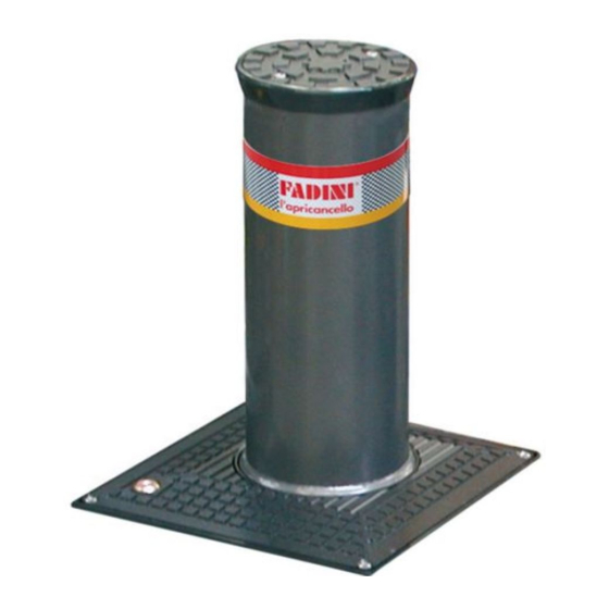
- Page 2 This product can be classified as a type of automated bollard, fully retractable into the ground. It is easy and simple to install as no special adjusting or calibration is required. The main application is traffic control. VIGILO 2250 is an electro-hydraulically operated post having a Ø...
- Page 3 PRELIMINARY OPERATION: SEPARATION OF THE POST ASSEMBLY First operation. Once the enclosure cover plate is removed, you can have access to the mechanism, and the components ie. the inner motor pump and actuator assembly can be easily lifted out using mechanical aid. Pic.2 IMPORTANT: make sure the electric cables are not damaged or accidentally removed from termination.
- Page 4 PIC. 4 - A hole will be required in the road surface where Vigilo 2250 is to be located, as indicated in Pic. 5. Provision is made within the unit for the entry of a Ø 50 mm duct to the electronic control unit (the cables are 10 m long). Provide a soakaway by pouring shingle into the hole up to 15 cm from bottom level.
- Page 5 - Once located the enclosure into the pit, it is important that the IMPORTANT: Once the installation Concrete foundation operations are completed the top edge is flush with the ground level. enclosure top edge must be flush - Fill with soil up to 55 cm and the remaining 30 cm with concrete with road surface Pic.
- Page 6 ELECTRICAL CONNECTIONS TO THE CONTROL UNIT ELPRO 10 PLUS CEI Vigilo 2250 is supplied fitted with two cables: one for the 230V 50Hz electric motor, the other cable should be connected to terminals 9 and 10 , limit switch Open (Pic.8) The electric motor should be connected as indicated in the diagram, a 20μF capacitor in parallel with the two live terminals.
-
Page 7: Electrical Wiring Diagram
5 - Elpro 10 PLUS CEI electronic control unit 6 - Electrical junction box 7 - Differential magnetic thermal mains switch (rating 30mA , protection 6-10A) 8 - Polo 44 photo cell receiver PIC. 9 9 - Bollard Vigilo 2250 10 - Jubi 433 transmitter... - Page 8 230/400V ELPRO 10 PLUS CEI F6=630mA 24V protection PULIN 3 EXT TIME (electric lock and courtesy light) from 2 to 255s TRANSFORMER DIP-SWITCH F4=630mA Transformer protection PEDESTRIAN OPENING TIME from 3 to 30s 4 5 6 7 8 RADIO PLUG-IN F5=1A flashing lamp CARD CONNECTOR DWELL TIME...
- Page 9 LOW VOLTAGE ELECTRICAL CONNECTIONS Photocells and Safety Edge: Button switch: Limit switch: DIP-SWITCH 1: ON: Photocells stop gate while opening, 12 13 reverse it on closing once obstacle is removed 24V OUTPUT (MAX. LOAD: PHOTOCELLS AND 2 PAIRS PHOTOCELLS OFF: Photocells do not stop gate while SAFETY EDGE opening, reverse it on closing in 1 RADIO RECEIVER)
- Page 10 Limit Switch Contact Light Access Blocked (Red Light Illuminated) Mains Limit Mains switch Supply Bollard VIGILO 2250 N.C. 230V 50Hz Fuse 2A Interface for the electrical connections of the green/red traffic lights PIC. 12 IMPORTANT: For security reasons, failure of the red...
-
Page 11: Manual Release System
MANUAL RELEASE SYSTEM In events like power failure, it is possible to manually operate the bollard by following the instructions in picture 13: first unscrew the Release Plug (1), locate the Release Spanner into the over-ride valve (2) and rotate anti-clockwise by one turn to over-ride the hydraulic circuit (3);... -
Page 12: Technical Specifications
AUTOMATIC GATE MANUFACTURERS The manufacturers reserve the right to change the products without any previous notice Via Mantova, 177/A - 37053 Cerea (Verona) Italy - Tel. +39 0442 330422 r.a. - Fax +39 0442 331054 - e-mail: info@fadini.net - www.fadini.net...
Need help?
Do you have a question about the Vigilo 2250 and is the answer not in the manual?
Questions and answers