Table of Contents
Advertisement
Advertisement
Table of Contents

Related Manuals for HUSABERG FE 450 AUS 2009


Summary of Contents for HUSABERG FE 450 AUS 2009
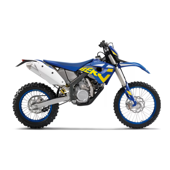
- Page 1 SETUP INSTRUCTIONS FE 450 AUS FE 570 AUS 2009 ART. NO. 3802015en...
- Page 3 HUSABERG accepts no liability for delivery options, deviations from illustrations and descriptions, as well as misprints and other errors.
-
Page 4: Means Of Representation
MEANS OF REPRESENTATION Symbols used The symbols used are explained in the following. Indicates an expected reaction (e.g. of a work step or a function). Indicates an unexpected reaction (e.g. of a work step or a function). Identifies a page reference (more information is provided on the specified page). Formats used The typographical and other formats used are explained in the following. - Page 5 SET‑UP Unpacking and setting up the vehicle – Remove the box and the plastic packaging. Info To avoid damaging the motorcycle during assembly, leave the protective film on the vehicle until you have finished. – Check the vehicle for transport damage. –...
- Page 6 SET‑UP – Position the mirror clamp – Position the clutch master cylinder and tighten the screw. – Mount both rear mirrors. – Tighten the screws of the mirror clamp. 100472-10 – Position the brake line and wiring harness in brake line guide ...
- Page 7 SET‑UP – Fix the handlebar cushion with cable binder 100477-10 – Mount the reflector. 100480-10 – Mount the footrests with the springs and bolts. Secure the bolts using the washers and pins. Plier for footrest spring (58429083000) – Install the engine guard. ( p.
- Page 8 WORK Installing the shock absorber – Push splash protector to the side and position the shock absorber. Mount and tighten screw Guideline Screw, top shock absorber 80 Nm Loctite ® 243™ (59 lbf ft) – Mount and tighten screw ...
-
Page 9: Installing The Engine Guard
WORK – Lift the front wheel into the fork, position it, and insert the wheel spindle. – Mount and tighten screw Guideline Screw, front wheel spindle M24x1.5 45 Nm (33.2 lbf ft) – Operate the hand brake lever several times until the brake pads are lying correctly on the brake disc. - Page 10 If the vehicle is not ridden for more than two weeks, we recommend trickle 100425-10 charging the battery with the HUSABERG battery charger. The battery is first charged completely and then maintained at this level over the subse- quent period. Thus, the battery is always fully charged when the vehicle is...
-
Page 11: Setting Kilometers Or Miles
WORK – Connect the negative cable. Info Contact disk must be mounted between battery terminal and cable socket with the claws facing up. – Tighten the screw. Guideline Screw, battery terminal 3 Nm (2.2 lbf ft) – Mount the seat. - Page 12 WORK Opening the filler cap 3.10 – Press release button , turn filler cap counterclockwise and lift it free. 100359-10 Closing the filler cap 3.11 – Replace the filler cap and turn clockwise until the release button locks in place. ...
-
Page 13: Technical Data - Tightening Torques For Chassis
TECHNICAL DATA - TIGHTENING TORQUES FOR CHASSIS – Spoke nipple, front wheel M4.5 5 Nm (3.7 lbf ft) – Screw, battery terminal 3 Nm (2.2 lbf ft) – Screw, intake air temperature sensor 2 Nm (1.5 lbf ft) – Spoke nipple, rear wheel 5 Nm (3.7 lbf ft) –... - Page 14 SUBSTANCES Super unleaded (ROZ 95 / RON 95 / PON 91) According to – DIN EN 228 (ROZ 95 / RON 95 / PON 91)
-
Page 15: Auxiliary Substances
AUXILIARY SUBSTANCES Long-life grease Specification – ® HUSABERG recommends Motorex products. Supplier ® Motorex – Fett 2000... - Page 17 HUSABERG eine Division der KTM SMC AG Stallhofnerstraße 3 5230 Mattighofen, Austria www.husaberg.com *3802015en* 3802015en...
Need help?
Do you have a question about the FE 450 AUS 2009 and is the answer not in the manual?
Questions and answers