TFT TORNADO Instructions For Installation, Safe Operation And Maintenance
Maximum recommended flow is 500 gpm 1900 l/min, maximum recommended pressure is 200 psi 14 bar
Hide thumbs
Also See for TORNADO:
Table of Contents
Advertisement
INSTRUCTIONS FOR INSTALLATION, SAFE OPERATION AND MAINTENANCE
DANGER
TORNADO
TASK FORCE TIPS, Inc.
MADE IN USA • www.tft.com
©Copyright Task Force Tips, Inc. 2005-2007
®
Read instruction manual before use. Operation of this device without
understanding the manual and receiving proper training is a misuse of this
equipment. A person who has not read and understood all operating and safety
instructions is not qualified to operate the Tornado or Tornado RC Monitor.
TM
MANUAL: TORNADO
& TORNADO RC MONITOR
Maximum Recommended Flow
is 500 gpm (1900 l/min)
Maximum Recommended Pressure
is 200 psi (14 bar)
TORNADO RC
2800 E Evans Ave, Valparaiso, IN 46383-6940 USA
800-348-2686 • 219-462-6161 • Fax 219-464-7155
TM
LIY-300 May 8, 2007 Rev04
Advertisement
Table of Contents

Related Manuals for TFT TORNADO


Summary of Contents for TFT TORNADO
- Page 1 A person who has not read and understood all operating and safety instructions is not qualified to operate the Tornado or Tornado RC Monitor. Maximum Recommended Flow...
-
Page 2: Table Of Contents
Stacked Tips Flow 5.1.2 Electrical Wiring 6.4.2 Tornado Monitor and Stream Straightener Friction Loss 5.1.3 Inputs Signal Configuration 6.5 Stream Straighteners ........27 5.1.4... -
Page 3: Meaning Of Safety Signal Words
3.0 GENERAL INFORMATION The Tornado monitor is a 2-inch, 500 gpm maximum monitor. It is available in a manually operated model as well as an electric remote controlled model. The electric remote controlled model is known as the Tornado RC. Further specifications are shown in the following sections. -
Page 4: Part Identification And Models
Europe ......N/A ....ETSI 3.2 PART IDENTIFICATION AND MODELS The Tornado and Tornado RC Monitor are shown in figs 3.2A and 3.2B along with the names of some various parts and controls. MANUAL OVERRIDE KNOB... -
Page 5: Inlets And Outlets5
1.5” NH 2.5” BSP MALE MALE MALE (Y2320ANJ) (Y2420ANF) (Y2420ABJ) INLET COUPLING 2.5 - 7.5 NH MANUAL TORNADO (TILLER BAR) MODEL TORNADO RC MODEL 2.5” BSP 2.0” BSP 2.5” ANSI 150 2.5” NPT 2.0” NPT 3.0” NPT CODE-RLF FEMALE FEMALE... -
Page 6: Overall Dimensions
(315 mm) (315 mm) See table below for additional height See table below for additional height from Inlet Fitting from Inlet Fitting Manual Tornado Monitor Dimensions Electric Tornado RC Monitor Dimensions Fig 3.4A Fig 3.4B MODEL INLET FITTING ADDITIONAL TYPE... -
Page 7: Electrical Controls
3.5.7 SMART STREAM TECHNOLOGY This technology, only available with TFT RC nozzles, utilizes a position encoder in the nozzle actuator to give the user greater control on the stream pattern, especially at FOG position. Nozzles equipped with a FLUSH position are programmed to stop and pause at full FOG position when moving towards the FLUSH position, preventing unwanted water flow. -
Page 8: Quick Connect Inlet Mounting And Travel Ranges
4.2 QUICK CONNECT INLET MOUNTING AND TRAVEL RANGES Figure 3.3 shows the various Inlet Adapters used on the Tornado. These Inlet Adapters must be oriented upon installation so the Tornado will point in the desired direction. Figure 4.2A shows examples of Inlet Adaptors and the location of a “Straight Ahead Reference Mark”. -
Page 9: Nozzle Installation
The nozzle is simply screwed onto the monitor's exit threads. For nozzles with electric pattern control, a cable with a female, waterproof connector is provided at the outlet of the Tornado RC which attaches directly to several of TFT's electric nozzles. The cable used is a dual-key, micro type plug assembly. Any other nozzle should have the corresponding male electrical connector installed. -
Page 11: Panel Mount Monitor Operator Station
5.1 PANEL MONITOR OPERATOR STATION (Y4E-RP) This operator station allows the monitor to be controlled from a remote location. The installer will need to mount the operator station and connect the cable to the monitor and power. The enclosure is designed to be recess mounted in a panel. This operator station has extra power and communication terminal blocks available and can be used as a central location for terminating wires. -
Page 12: Inputs Signal Configuration
5.1.3 INPUTS SIGNAL CONFIGURATION The Panel Mount Operator Station is shipped from the factory configured to accept ground input signals , but can be field changed to accept +12/24 volt DC input signals . To change the configuration: 1. Remove lid from enclosure. 2. -
Page 13: Tether Monitor Operator Stations
5.2 TETHER MONITOR OPERATOR STATION (Y4E-CT-##) This operator station will have a factory installed 4-conductor cable, which will act as a tether, with a plug on the end. The installer will need to mount the holster and receptacle. The holster is supplied with(3) 1/4-20 stainless steel self-tapping screws. Make sure the material beneath the bracket is substantial and thick enough to hold self-tapping screws. -
Page 14: Wireless Monitor Operator Station
5.3 WIRELESS MONITOR OPERATOR STATION (YE-RF-##) The YE-RF-## Wireless Operator Station is supplied with a radio board that needs to be installed in the monitor control box and a storage bracket. 5.3.1 MOUNTING STORAGE BRACKET The storage bracket is supplied with (3) 1/4-20 stainless steel self-tapping screws. Make sure the material beneath the bracket is substantial and thick enough to hold self-tapping screws. -
Page 15: Teaching Id Code
NOZZLE STOPS AT FULL FOG PRESS AGAIN FOR FLUSH FUNCTION 2-27/32 TRIGGER (72 mm) ® HOLE MOUNTING DETAIL TASK FORCE TIPS 800-348-2686 • www.tft.com FIRE FIGHTING EQUIPMENT Y5336 Fig 5.4.1.1 Fig 5.4.1.2 Joystick Operator Station Hole Dimensions Joystick Instruction Label... -
Page 16: Electrical Wiring
5.4.2 ELECTRICAL WIRING The joystick operator station must be connected to the included Y4E-COMM Communication Interface Box or a separately supplied Y4E-RP Panel Mount Operator Station. By connecting the joystick to a communication interface box, a panel mount operator station is not required and the installer has the option to enable the joystick operator station with the master override feature (see Section 6.2.2). -
Page 17: Toggle Switch Monitor Operator Station
5.5 TOGGLE SWITCH MONITOR OPERATOR STATION (Y4E-TS) This operator station allows the monitor to be controlled by three toggle switches. The installer will need to mount the operator station and connect the cable to the monitor and power. 5.5.1 ENCLOSURE MOUNTING Select proper operator location. -
Page 18: Communication Interface Box With At Stow Relay
5.6.3 INPUTS SIGNAL CONFIGURATION The Communication Interface Box is shipped from the factory configured to accept +12/24 volt DC input signals, but can be field changed to accept ground input signals. To change the configuration: 1. Remove lid from enclosure. 2. -
Page 19: Monitor Position Display
5.7 MONITOR POSITION DISPLAY (Y4E-DISP) The monitor position display is supplied with a 10' (3 m) long 4-conductor cable. The installer will need to surface mount the enclosure in a dry area and connect the cable to power and the communication link of the monitor. Display is designed for use with 180° total horizontal axis travel. -
Page 20: Connecting Monitor Cable Directly To Protected
5.8.3 CONFIGURATION The two relays on the circuit board can be individually configured as AUX1 or AUX2. Also the actuation of each relay can be configured to be momentary or latched. See Figure 5.9.3 for relay configuration DIP switch settings. Remove lid from interface box. -
Page 21: Ladder Installation Electrical Wiring
5.10.2.1 LADDER INSTALLATION ELECTRICAL WIRING (-L MODELS) The electronics enclosure converts discrete input signals into serial communications for controlling the monitor. The discrete input signals can be from a joystick, toggle switches, relay contacts or Canbus output module. The electronic interface accepts +12/24 VDC signals, but can be field changed to accept ground signals. -
Page 22: Platform Installation Electrical Wiring
5.10.2.2 PLATFORM INSTALLATION ELECTRICAL WIRING (-P MODELS) The electronics enclosure converts discrete input signals into serial communications for controlling the monitor. The discrete input signals can be from a joystick, toggle switches, relay contacts or Canbus output module. The electronic interface accepts +12/24 VDC signals, but can be field changed to accept ground signals. -
Page 23: Electric Connections
Please consult factory for installation. 6.0 OPERATION 6.1 OVERRIDE HANDWHEELS In the event of electrical system failure of the monitor or fire truck, Tornado RC is factory supplied with handwheels so the monitor may be manually operated. 6.2 ELECTRICAL MODEL 6.2.1 OPERATOR STATIONS... -
Page 24: Tether Operator Station
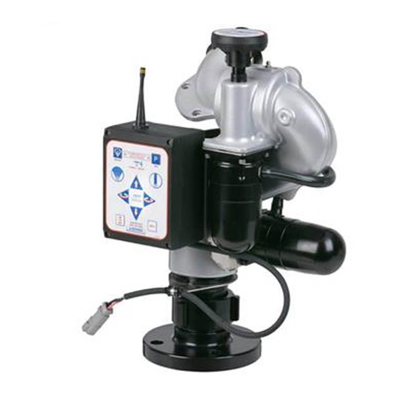
The Wireless Operator Station allows a user to move away from the truck to get a better view for redirecting the monitor. This operator station gives the user full control of the monitor including the STOW, OSCillate, and any AUXiliary functions. Every TFT RC monitor is shipped with the antenna pre-mounted in the monitor control box. -
Page 25: Stow Programming Example
Move monitor to 2nd point, press OSC button. LED will blink rapidly to acknowledge position. Repeat until pattern is complete. 800-348-2686 Press & hold OSC button until LED turns off. www.tft.com NOTE: PATTERN WILL BE CLEARED UPON POWER LOSS. Y5705 Figure 6.2.4.1 Operator Station Label 6.2.4.2 OSCILLATE PATTERN RETAIN FEATURE (DIP #4) -
Page 26: Operator Station Panels
Fig 6.2.5 Operator Station Button Layouts 6.2.6 OVERRIDE KNOBS In the event of electrical system failure on the monitor or fire apparatus, the Tornado RC 11/16” Monitor is factory supplied with override knobs so the monitor may be manually operated. -
Page 27: Tornado Monitor And Stream Straightener Friction Loss
6.5.1 STREAM STRAIGHTENERS WITH STACKED TIP NOZZLES Turbulence though the Tornado Monitor is very low, but stream quality and reach can be improved with the use of a stream straightener on the TFT stacked tip nozzle. See figure 6.4.2 for the TFT stream straightener friction loss. -
Page 28: Troubleshooting
8.0 TROUBLESHOOTING SYMPTOM POSSIBLE CAUSE REMEDY Leaks Debris or damage in seal area Clean out debris or replace damaged parts Elevation Binding Debris or damage to elevation drive parts Clean out debris or replace damaged parts Lack of lubricant Grease, see section 8.1 Horizontal Rotation Binding Debris or damage to horizontal drive parts Clean out debris or replace damaged parts... - Page 29 SYMPTOM POSSIBLE CAUSE REMEDY STOW & OSC LED’s on Loosen encoder wiring connection. Check axis encoder connection. monitor control station blink rapidly when button pressed. Bad motor encoder. Interchange motor control boards. Check if problem persists with same axis. If yes, replace motor. Remove encoder cover and check for RED light just below disk.
-
Page 30: Drawings And Parts List
9.0 TORNADO DRAWING & PARTS LIST Fig 9.0A Manual Tornado Exploded View... - Page 31 1/4-28 X ½ SOCKET SET SCREW VT25-28SS500 BASE TILLER ALUMINUM Y2410A O-RING-233 2-7/8 ID X 1/8 C/S VO-233 1/4-28 X ½ BUTTON HEAD CAP SCREW VT25-28BH500 NAME LABEL: TORNADO MONITOR Y2124 LABEL BRACKET Y2120 3/8-24 X 3/8 DOG POINT H515 WEAR DISC Y4191...
- Page 32 9.0 TORNADO RC DRAWING & PARTS LIST Fig 9.0B Tornado RC Exploded View...
- Page 33 BASE - QUICK CONNECT ALUMINUM Y2415A O-RING-233 2-7/8 ID VO-233 1/4-28 X ½ BUTTON HEAD CAP SCREW VT25-28BH500 LABEL BRACKET Y2120 NAME LABEL: TORNADO RC Y2122 1/4-20 X ½ BUTTON HEAD CAP SCREW VT25-20BH500 OVERRIDE KNOB Y4165 LOWER SECTION RC ALUMINUM Y2110A THREAD ADAPTER 2.5"NH MALE ALUMINUM...
- Page 34 9.0 TORNADO RC DRAWING & PARTS LIST POWER CABLE TO TFT ER NOZZLE MALE PLUG TO HORIZONTAL GEAR MOTOR TO VERTICAL GEAR MOTOR DESCRIPTION QTY. PART NO. CABLE FITTING PG11 Y5205 CABLE FITTING PG9 Y5245 ENCLOSURE - BOX Y5115 LOCKNUT - PG9...
- Page 35 9.0 TORNADO RC DRAWING & PARTS LIST DESCRIPTION PART # 6-32 x 5/16 LONG SHCS WITH HEAD SEAL VT06S32SH312 CUP SEAL 1.0625 x .5625 x 1/4 Y4620 MOTOR SOCKET, ANGLED FITTING Y4617 O-RING-018, 3/4 ID 1/16 CS VO-018 CONDUIT FITTING Y5213 HOSE - 3/8"...
-
Page 36: Warranty
TFT, at 2800 East Evans Avenue, Valparaiso, Indiana 46383-6940, within a reasonable time after discovery of the defect. TFT will examine the equipment. If TFT determines that there is a defect attributable to it, it will correct the problem within a reasonable time. If the equipment is covered by this limited warranty, TFT will assume the expenses of repair.
Need help?
Do you have a question about the TORNADO and is the answer not in the manual?
Questions and answers