Table of Contents
Advertisement
Quick Links
INSTRUCTIONS FOR INSTALLATION, SAFE OPERATION AND MAINTENANCE
DANGER
Maximum recommended inlet
pressure is 200 psi. (14 bar)
DANGER
PERSONAL RESPONSIBILITY CODE
The member companies of FEMSA that provide emergency response
equipment and services want responders to know and understand the
following:
1. Firefighting and Emergency Response are inherently dangerous
activities requiring proper training in their hazards and the use of extreme
caution at all times.
2. It is your responsibility to read and understand any user's instructions,
including purpose and limitations, provided with any piece of equipment
you may be called upon to use.
3. It is your responsibility to know that you have been properly trained in
Firefighting and /or Emergency Response and in the use, precautions,
and care of any equipment you may be called upon to use.
4. It is your responsibility to be in proper physical condition and to maintain
the personal skill level required to operate any equipment you may be
called upon to use.
5. It is your responsibility to know that your equipment is in operable
condition and has been maintained in accordance with the
manufacturer's instructions.
6. Failure to follow these guidelines may result in death, burns or other
severe injury.
FEMSA
Fire and Emergency Manufacturers and Services Association, Inc.
P.O. Box 147, Lynnfield, MA 01940 • www.FEMSA.org
TASK FORCE TIPS, Inc.
MADE IN USA • www.tft.com
©Copyright Task Force Tips, Inc. 2004-2007
MANUAL: Remote Control
®
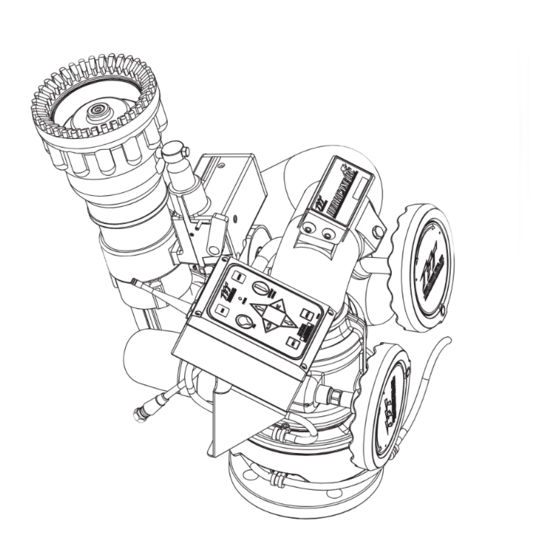
HURRICANE RC MONITOR
Read instruction manual before use. Operation of this device without understanding the manual
and receiving proper training is a misuse of this equipment. A person who has not read and
understood all operating and safety instructions is not qualified to operate the Hurricane RC
monitor.
Model XFIH-E11A Monitor
This instruction manual is intended to familiarize installers,
firefighters and maintenance personnel with the installation,
operation, servicing, and safety procedures associated with
the Hurricane RC Monitor.
This manual should be kept available to all operating and
maintenance personnel.
2800 E. Evans Ave., Valparaiso, IN 46383-6940 USA
800-348-2686 • 219-462-6161 • Fax 219-464-7155
Shown With
Model M-ERP-NJ Nozzle
LIX-300 August 17, 2007 Rev08
Advertisement
Table of Contents

Related Manuals for TFT XFIH-E11A


Summary of Contents for TFT XFIH-E11A
- Page 1 P.O. Box 147, Lynnfield, MA 01940 • www.FEMSA.org TASK FORCE TIPS, Inc. 2800 E. Evans Ave., Valparaiso, IN 46383-6940 USA 800-348-2686 • 219-462-6161 • Fax 219-464-7155 MADE IN USA • www.tft.com ©Copyright Task Force Tips, Inc. 2004-2007 LIX-300 August 17, 2007 Rev08...
-
Page 2: Table Of Contents
Table of Contents 1.0 MEANING OF SAFETY SIGNAL WORDS ......3 5.9 CONNECTING MONITOR CABLE DIRECTLY TO PROTECTED POWER . -
Page 3: Meaning Of Safety Signal Words
Motors and control boxes are factory tested for water tightness. Available with various inlet adapters for flanges and thread fittings. Inlet also made for direct connection to TFT's Extend-A-Gun RC3 or RC4. Standard outlet is 2-½” National Hose male (65mm). Other outlets are available (see figure 3.3). -
Page 4: Electrical Specifications
3.1.2 ELECTRICAL SPECIFICATIONS Nominal Operating voltage: 12 or 24 VDC (field changeable) Motor current: Nominal* Limit Elevation motor: 6 amps 15 amps Horizontal rotation motor: 6 amps 10 amps Nozzle motor: 1 amp 5 amps *with rated water pressure applied At rest current: .25 amps Recommended fuse or circuit breaker size:... -
Page 5: Inlets And Outlets
3.3 INLETS AND OUTLETS The standard Hurricane RC Monitor inlet is CODE-RLF for direct connection to TFT's Extend-A-Gun RC3. Monitor inlet CODE-RPF is available for direct connection to Extend-A-Gun RC4. The standard outlet is 2-½”-6 National Hose male. Various other inlet and outlet fittings are available as shown in Figure 3.3. -
Page 6: Inlet Flange Size Specifications
3.3.1 INLET FLANGE SIZE SPECIFICATIONS MODEL FITS FLANGE OUTSIDE THICKNESS BOLT HOLE NO. BOLT SIZE OF TORQUE ON BOLTS DIAMETER CIRCLE HOLES BOLTS XFIH-E1*A 3” ANSI 125/150 7.5” .75" 6.0" 5/8" 76-80 FT-LBF (metric DN8 PN20) 190mm 20mm 152.5mm 100-110 Newton Meters XFIH-E2*A 4"... -
Page 7: Electrical Controls
3.5.7 SMART STREAM TECHNOLOGY This technology, only available with TFT RC nozzles, utilizes a position encoder in the nozzle actuator to give the user greater control on the stream pattern, especially at FOG position. Nozzles equipped with a FLUSH position are programmed to stop and pause at full FOG position when moving towards the FLUSH position, preventing unwanted water flow. -
Page 8: Inlet Fittings Or Extend-A-Gun Rc Installation
The Hurricane RC Monitor is available with various inlet fittings as shown in figure 3.3. The Hurricane RC Monitor also connects directly to TFT's Extend-A-Gun RC3 or RC4. The fittings and Extend-A-Gun RC are attached to the monitor by means of a threaded joint with an o-ring seal. - Page 9 The Extend-A-Gun RC manual override knob may be mounted in any one of four possible orientations (90 degrees apart). MANUAL OVERRIDE KNOB ON EXTEND-A-GUN STRAIGHT BACK REFERENCE MARK 1-1/2 TURNS (SEE FIGURE 4.2A) APPROX. 37 IN. 3/4 TURNS APPROX. 33 IN. 1 TURN APPROX.
-
Page 10: Nozzle Connection
For nozzles with electric pattern control, a waterproof connector wire is provided at the bottom outlet of the Hurricane RC's control station box. This wire attaches directly to TFT's electric Masterstream 1250 nozzle. The electric actuator box of nozzle must be oriented to the top side of nozzle for the connection wire to extend 90°... -
Page 11: Pressure Gage Port
FIG 4.4A Horizontal Travel Limits Pry out plastic plug and install Stop Bolt(s) to obtain desired travel limits. (TFT# Y4145) 45 LEFT ° ° RIGHT 90 LEFT ° ° RIGHT 135 LEFT AND RIGHT ° FIG 4.4B (ONLY ONE STOP BOLT... -
Page 12: Electrical Controls Installation
5.0 ELECTRICAL CONTROLS INSTALLATION The electric RC monitor is supplied with a monitor mounted operator station. The wiring on the monitor and for this operator station is factory installed. The assembly is supplied with a 30-foot length of cable for connection to the operator control stations as shown in Figure 5.0 or directly to a protected voltage supply. -
Page 14: Primary Monitor Operator Station
5.1 PANEL MONITOR OPERATOR STATION (Y4E-RP) This operator station allows the monitor to be controlled from a remote location. The installer will need to mount the operator station and connect the cable to the monitor and power. The enclosure is designed to be recess mounted in a panel. This operator station has extra power and communication terminal blocks available and can be used as a central location for terminating wires. -
Page 15: Input Signal Configuration
5.1.3 INPUTS SIGNAL CONFIGURATION The Panel Mount Operator Station is shipped from the factory configured to accept ground input signals , but can be field changed to accept +12/24 volt DC input signals . To change the configuration: 1. Remove lid from enclosure. 2. -
Page 16: Tether Monitor Operator Station
5.2 TETHER MONITOR OPERATOR STATION (Y4E-CT-##) This operator station will have a factory installed 4-conductor cable, which will act as a tether, with a plug on the end. The installer will need to mount the holster and receptacle. The holster is supplied with(3) 1/4-20 stainless steel self-tapping screws. Make sure the material beneath the bracket is substantial and thick enough to hold self-tapping screws. -
Page 17: Wireless Monitor Operator Station
5.3 WIRELESS MONITOR OPERATOR STATION (YE-RF-##) The YE-RF-## Wireless Operator Station is supplied with a radio board that needs to be installed in the monitor control box and a storage bracket. 5.3.1 MOUNTING STORAGE BRACKET The storage bracket is supplied with (3) 1/4-20 stainless steel self-tapping screws. Make sure the material beneath the bracket is substantial and thick enough to hold self-tapping screws. -
Page 18: Teaching Id Code
Repeat until pattern is complete. Press & hold OSC button until LED turns off. NOTE: PATTERN WILL BE CLEARED UPON POWER LOSS. ® TASK FORCE TIPS Where New Ideas Flow™ • 800-348-2686 • www.tft.com FIRE FIGHTING EQUIPMENT Y5336 Fig 5.4.1.1 Fig 5.4.1.2... -
Page 19: Toggle Switch Monitor Operator Station
5.5 TOGGLE SWITCH MONITOR OPERATOR STATION (Y4E-TS) This operator station allows the monitor to be controlled by three toggle switches. The installer will need to mount the operator station and connect the cable to the monitor and power. 5.5.1 ENCLOSURE MOUNTING Select proper operator location. -
Page 20: Input Signal Configuration
5.6.3 INPUTS SIGNAL CONFIGURATION The Communication Interface Box is shipped from the factory configured to accept +12/24 volt DC input signals, but can be field changed to accept ground input signals. To change the configuration: 1. Remove lid from enclosure. 2. -
Page 21: Monitor Position Display
5.7 MONITOR POSITION DISPLAY (Y4E-DISP) The monitor position display is supplied with a 10' (3 m) long 4-conductor cable. The installer will need to surface mount the enclosure in a dry area and connect the cable to power and the communication link of the monitor. Display is designed for use with 180° total horizontal axis travel. -
Page 22: Connecting Monitor Cable Directly To Protected Power Supply
5.8.3 CONFIGURATION The two relays on the circuit board can be individually configured as AUX1 or AUX2. Also the actuation of each relay can be configured to be momentary or latched. See Figure 5.9.3 for relay configuration DIP switch settings. Remove lid from interface box. -
Page 23: Hurricane Rc Aerial Truck Installation
5.10.2.1 LADDER INSTALLATION ELECTRICAL WIRING (-L MODELS) The electronics enclosure converts discrete input signals into serial communications for controlling the monitor. The discrete input signals can be from a joystick, toggle switches, relay contacts or Canbus output module. The electronic interface accepts +12/24 VDC signals, but can be field changed to accept ground signals. -
Page 24: Platform Installation Electrical Wiring
5.10.2.2 PLATFORM INSTALLATION ELECTRICAL WIRING (-P MODELS) The electronics enclosure converts discrete input signals into serial communications for controlling the monitor. The discrete input signals can be from a joystick, toggle switches, relay contacts or Canbus output module. The electronic interface accepts +12/24 VDC signals, but can be field changed to accept ground signals. -
Page 25: Electrical Nozzle Actuator Wiring
5.11 ELECTRIC NOZZLE ACTUATOR WIRING The electric RC monitor is designed to control and is factory wired for a TFT electric actuated nozzle. Task Force Tips nozzles are available with a male cord plug. After mounting the appropriate nozzle onto the monitor, plug the male cord from the nozzle into the female cord located on the outlet of the monitor. -
Page 26: Operation
The Wireless Operator Station allows a user to move away from the truck to get a better view for redirecting the monitor. This operator station gives the user full control of the monitor including the STOW, OSCillate, and any AUXiliary functions. Every TFT RC monitor is shipped with the antenna pre-mounted in the monitor control box. -
Page 27: Joystick Operator Station
6.2.1.5 JOYSTICK OPERATOR STATION (Y4E-JS) This operator station is installed in a protected location and allows the monitor to be controlled by a joystick. 6.2.1.6 TOGGLE SWITCH OPERATOR STATION (Y4E-TS) This operator station allows the monitor to be operated by three toggle switches. 6.2.2 MASTER OVERRIDE FEATURE (DIP #1) Any operator station with a communication board can be reconfigured with the master override feature. -
Page 28: Stow Programming Example
Move monitor to 2nd point, press OSC button. LED will blink rapidly to acknowledge position. Repeat until pattern is complete. 800-348-2686 Press & hold OSC button until LED turns off. www.tft.com NOTE: PATTERN WILL BE CLEARED UPON POWER LOSS. Y5705 Figure 6.2.4.1 Operator Station Label 6.2.4.2 OSCILLATE PATTERN RETAIN FEATURE (DIP #4) -
Page 29: Operator Station Panels
6.2.5 OPERATOR STATION PANELS The operator stations are all equipped with the same monitor movement functions. From the operator stations, the operator can command the monitor up, down, left, right and command the nozzle pattern shaper from fog to straight stream. Operator stations supplied with the membrane switch, shown on the left below, allow the operator to program and perform the oscillate and stow features. -
Page 30: Stacked Tips Flow And Reach
6.5.1 STACKED TIPS FLOW AND REACH English Units Nozzle Pressure (PSI) Nozzle Diameter Flow Reaction Flow Reaction Flow Reaction Flow Reaction (inches) GPM 1 bar = 14.5 psi 1.375 1 gal = 3.785 l/min 1.50 1.75 2.00 1060 1190 Metric Units Nozzle Pressure (BAR) Nozzle Diameter Flow... - Page 31 1.375 INCH TIP HORIZONTAL DISTANCE (M) 20.0 40.0 60.0 80.0 60 PSI 80 PSI 100 PSI 40 PSI 40.0 80.0 120.0 160.0 200.0 240.0 280.0 HORIZONTAL DISTANCE (FEET) 1.50 INCH TIP HORIZONTAL DISTANCE (M) 20.0 40.0 60.0 80.0 60 PSI 80 PSI 100 PSI 40 PSI...
- Page 32 HORIZONTAL DISTANCE (METERS) 75 DEGREES 2.0 INCH TIP, 100 PSI, 1190 GPM 60 DEGREES 45 DEGREES 30 DEGREES HORIZONTAL DISTANCE (FEET) This graph is approximate only. Critical applications should be tested in actual conditions to verify adequate reach. FIG 6.5.1D Effects Of Elevation Of Trajectory 2.00 INCH TIP , 100 PSI, 1190 GPM HORIZONTAL DISTANCE (M)
-
Page 33: Automatic Nozzles
Automatic nozzles maintain a constant pressure by adjusting their orifice to match the available flow. Consult the nozzle’s manufacturer for maximum flow and pressure ratings. In all cases, do not exceed 1250 gpm (4500 l/min). TFT's Masterstream 1250 Nozzle has a 150-1250 gpm (600 - 4500 l/min) flow range. Masterstream 1250 Nozzle operating instructions (Item Number LIM-030) are available on TFT's website: www.tft.com... -
Page 34: Troubleshooting
7.0 TROUBLE SHOOTING SYMPTOM POSSIBLE CAUSE REMEDY Leaks Debris or damage in seal area Clean out debris or replace damaged parts Elevation Binding Debris or damage to elevation drive parts Clean out debris or replace damaged parts Lack of lubricant Grease, see section 8.1 Horizontal Rotation Binding Debris or damage to horizontal drive parts... -
Page 35: Maintenance And Inspection
7.0 TROUBLE SHOOTING (continued) SYMPTOM POSSIBLE CAUSE REMEDY STOW & OSC Light’s on Loose encoder wiring connection. Check axis encoder connection. monitor control station blink rapidly when button pressed. Bad motor encoder. Interchange motor control boards. Check if problem persists with same axis. If yes, replace motor. Remove encoder cover and check for RED light just below disk. -
Page 36: Exploded View Drawings And Parts List
9.0 EXPLODED VIEW DRAWINGS AND PARTS LIST 9.1 HURRICANE RC MONITOR ASSEMBLY... - Page 37 HURRICANE RC MONITOR PARTS LIST DESCRIPTION PART # SHAFT NUT X210 SNAP RING VR4220 BEARING VM4250 WORM W/ KEYWAY X220 BELL / BIG BEND ASSEMBLY X806 GREASE FITTING 1/4-28 VT25-28ZERK HEX MOUNTING SCREW X258 CHAIN DRIVE ASSEMBLY X888 3/8-16 x 1 BHCS VT37-16BH1.0 LABEL BRACKET X395...
-
Page 38: Elevation Chain Drive Assembly
9.2 ELEVATION CHAIN DRIVE ASSEMBLY DESCRIPTION PART # HOUSING X250 BUSHING - SHAFT X251 BUSHING - DRIVE X252 ROLLER CHAIN RING X255 SPROCKET - SLAVE X254 SPROCKET - DRIVE X253 BUSHING - MOTOR X256 COVER X257 9.3 GEAR MOTOR ASSEMBLY 1/4-28 x ½... -
Page 39: Monitor Control Box Assembly
9.4 MONITOR CONTROL BOX ASSEMBLY POWER CABLE TO TFT ER NOZZLE MALE PLUG TO HORIZONTAL GEAR MOTOR TO VERTICAL GEAR MOTOR DESCRIPTION QTY. PART NO. CABLE FITTING PG11 Y5205 CABLE FITTING PG9 Y5245 ENCLOSURE - BOX Y5115 LOCKNUT - PG9... -
Page 40: Warranty
TFT, at 2800 East Evans Avenue, Valparaiso, Indiana 46383-6940, within a reasonable time after discovery of the defect. TFT will examine the equipment. If TFT determines that there is a defect attributable to it, it will correct the problem within a reasonable time.
Need help?
Do you have a question about the XFIH-E11A and is the answer not in the manual?
Questions and answers