Table of Contents
Advertisement
Quick Links
INSTRUCTIONS FOR INSTALLATION, SAFE OPERATION AND MAINTENANCE
DANGER
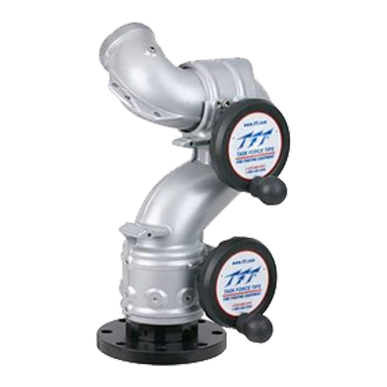
Typhoon Tiller
See Section 3.1 for Flow/Pressure
Operations Envelope
typhoon
typhoon rc
TASK FORCE TIPS LLC
MADE IN USA • tft.com
©Copyright Task Force Tips LLC 2004-2018
MANUAL: TYPHOON
& TYPHOON RC MONITOR
See Remote Control (RC) Monitor Electrical Controls Supple-
mental Instructions For Use With Typhoon RC Models
Understand manual before use. Operation of this device without understanding the manual and
receiving proper training is a misuse of this equipment. Obtain safety information at www.tft.
com/serial-number
Typhoon Tiller
With Handwheel Elevation
Typhoon RC
3701 Innovation Way, Valparaiso, IN 46383-9327 USA
800-348-2686 • 219-462-6161 • Fax 219-464-7155
Typhoon
Dual Handwheel
LIY-050 January 23, 2018 Rev13
Advertisement
Table of Contents

Related Manuals for TFT Typhoon


Summary of Contents for TFT Typhoon
- Page 1 INSTRUCTIONS FOR INSTALLATION, SAFE OPERATION AND MAINTENANCE Understand manual before use. Operation of this device without understanding the manual and DANGER receiving proper training is a misuse of this equipment. Obtain safety information at www.tft. com/serial-number Typhoon Tiller Typhoon Tiller...
- Page 2 DANGER PERSONAL RESPONSIBILITY CODE The member companies of FEMSA that provide emergency response equipment and services want responders to know and understand the following: 1. Firefi ghting and Emergency Response are inherently dangerous activities requiring proper training in their hazards and the use of extreme caution at all times.
-
Page 3: Table Of Contents
6.4.2 Stream Straighteners with Fog Nozzles 3.4 Overall Dimensions 7.0 FM Approval (Factory Mutual) .......27 4.0 Installation ............12-18 8.0 Typhoon Drawings and Parts List ....28-35 4.1 Structural Requirements for Monitor Mounting 8.1 Manual Typhoon Drawing 4.2 Inlet Mounting and Travel Ranges 8.2 Typhoon RC Drawing... -
Page 4: Meaning Of Safety Signal Words
DC power supplies with voltages from 12-24 VDC. Using the wrong power source may cause electrocution or ignition resulting in serious injury or death. The electric Typhoon RC may be remotely operated. The electric drives are current limited but CAUTION may still produce enough force to cause injury. -
Page 5: General Information
3.0 GENERAL INFORMATION The Typhoon monitor is a 4-inch monitor. It is available in various manually operated models as well as an electric remote model. The electric remote model is known as the Typhoon RC. 3.1 MECHANICAL SPECIFICATIONS Manual Electric... -
Page 6: Part Identification And Models
90° left and right (180° total). The various models of Typhoon monitors are shown in fi gures 3.2A, 3.2B, 3.2C and 3.2D. The monitor mounted control station on the standard remote controlled model is shown in fi... -
Page 7: Inlets And Outlets
3.3 INLETS AND OUTLETS 3.3.1 INLET OPTIONS AND ADDITIONAL HEIGHT Various other inlet and outlet options are available as shown in fi gure 3.3. 3.3.1.1 FLANGES Manual & Tiller Electric INLET PART MONITOR MONITOR ADDITIONAL QUICK PART ADDITIONAL ADDITIONAL OPTION # NUMBER INLET INLET BASE... -
Page 8: Outlet Options
3.3.1.4 MATING PRODUCTS Manual & Tiller Electric INLET PART MONITOR MONITOR ADDITIONAL QUICK PART ADDITIONAL ADDITIONAL OPTION # NUMBER INLET INLET BASE HEIGHT* CONNECT NUMBER HEIGHT* HEIGHT* ADAPTER OPTION # ** EXTEND-A- LIX-512 CODE-RLF GUN 3" 0.00 Y4487 3.83 6.58 EXTEND-A- LIX-530 CODE-RLF... -
Page 9: Overall Dimensions
3.4 OVERALL DIMENSIONS ©Copyright Task Force Tips LLC 2004-2018 LIY-050 January 23, 2018 Rev13... - Page 10 3.4 OVERALL DIMENSIONS 225° LEFT 225° LEFT 22.5° REF 225° RIGHT 225° RIGHT 9.1" [232mm] FLANGE BOLT HOLE ORIENTATION SWING RADIUS 90° 45° 21.1" [535mm] 18.4" [467mm] Typhoon RC Figure 3.4D ©Copyright Task Force Tips LLC 2004-2018 LIY-050 January 23, 2018 Rev13...
- Page 11 3.4 OVERALL DIMENSIONS 90° LEFT 90° RIGHT 9.1" [232mm] FLANGE BOLT HOLE ORIENTATION SWING RADIUS 45° 45° 19" [484mm] 16.4" [416mm] 4.7" [120mm] Typhoon RC for Platform Figure 3.4E ©Copyright Task Force Tips LLC 2004-2018 LIY-050 January 23, 2018 Rev13...
- Page 12 FLANGE BOLT HOLE ORIENTATION 45° 30° 90° 45° 19" [484mm] 16.4" [416mm] 7.5" Shown with anti back-drive mechanism. Can be ordered without [192mm] anti back-drive mechanism Typhoon RC for Ladder Figure 3.4F ©Copyright Task Force Tips LLC 2004-2018 LIY-050 January 23, 2018 Rev13...
-
Page 13: Installation
See Remote Control (RC) Monitor Electrical Controls Supplemental Instructions LIY-500. 4.1 STRUCTURAL REQUIREMENTS FOR MONITOR MOUNTING The structure that the Typhoon Monitor is mounted to must withstand the internal pressure of the monitor as well as shear and bending forces due to nozzle reaction. -
Page 14: Inlet Mounting And Travel Ranges
4.2.1 INLET FITTING OR EXTEND-A-GUN INSTALLATION The Typhoon Monitor is available with various inlet fi ttings as shown in fi g 3.3. When the inlet fi ttings are used see fi gure 4.2.1A for the addition to overall height. The Typhoon Monitor also connects directly to TFT’s Extend-A-Gun RC3 or RC4. The fi ttings and Extend-A-Gun RC are attached to the monitor by means of a threaded joint with an o-ring seal. - Page 15 Straight Ahead Reference Mark on the monitor. NOTE: Typhoon monitor, for use with Extend-A-Gun RC, comes with the wire installed in a nylon tube. The nylon tubing gives the wire additional stiff ness so it better follows as the Extend-A-Gun RC extends or retracts.
-
Page 16: Horizontal Rotation Travel Stops
4.2.2 HORIZONTAL ROTATION TRAVEL STOPS The range of horizontal rotation travel for the manual Typhoon monitor is continuous 360 degrees. The motorized version is limited to 450 degrees total horizontal rotation travel or 225 degrees from either side of a straight ahead position. Horizontal rotation travel stop bolts may be installed in the monitor to limit travel as shown in fi... -
Page 17: Elevation Travel Stops
4.2.3 ELEVATION TRAVEL STOPS The range of elevation travel for the Typhoon Monitor is 45 degrees past vertical to 45 degrees below horizontal. The elevation range may be limited by installing the supplied stop bolts and adjustment disks at the locations shown is fi gures 4.2.3A and 4.2.3B. Consult factory for other ranges. -
Page 18: Nozzle Installation
4.3 NOZZLE INSTALLATION The nozzle is simply screwed onto the monitor’s exit threads. If the nozzle is installed on a Typhoon RC (with electric motors) assure that the nozzle’s actuator does not make contact with the horizontal drive motor housing when the monitor is in it’s lowest elevation position. -
Page 19: Tiller Bar Model
5.5 OVERRIDE KNOBS In the event of electrical system failure on the monitor or fi re truck the Typhoon Monitor is factory supplied with knobs so the monitor may be manually operated. To make the Typhoon RC more compact the manual override knobs may be removed. The drive shafts have a hex so an 11/16”... -
Page 20: Flows And Pressures
1440 1660 1860 2.75 1590 1740 2010 — — 14.5 psi = 1 bar FLOW EXCEEDS RATING OF TYPHOON MONITOR 1 gpm = 3.785 l/min NOZZLE INLET PRESSURE Nozzle 3.5 BAR 4.1 BAR 5.5 BAR 7 BAR Diameter FLOW REACTION... - Page 21 2 INCH TIP HORIZONTAL DISTANCE (M) 20.0 40.0 60.0 80.0 60 PSI 80 PSI 100 PSI 50 PSI 40.0 80.0 120.0 160.0 200.0 240.0 280.0 HORIZONTAL DISTANCE (FEET) 2.25 INCH TIP HORIZONTAL DISTANCE (M) 20.0 40.0 60.0 80.0 60 PSI 80 PSI 100 PSI 50 PSI...
- Page 22 This graph is approximate only. Critical applications should be tested in actual conditions to verify adequate reach. 2.25 INCH TIP , 100 PSI, 1500 GPM HORIZONTAL DISTANCE (M) 75 DEGREES 60 DEGREES 45 DEGREES 30 DEGREES HORIZONTAL DISTANCE (FEET) Fig 6.1E Eff...
-
Page 23: Mst-4Nj Flow And Reach
6.1.1 MST-4NJ FLOW AND REACH 2" 1-3/4" 1-1/2" 1-3/8" 2.5” Coupling NOZZLE PRESSURE (PSI) NOZZLE DIAMETER FLOW REACTION FLOW REACTION FLOW REACTION FLOW REACTION (inches) (GPM) (LBS) (GPM) (LBS) (GPM) (LBS) (GPM) (LBS) 1.375 1.50 1.75 2.00 1000 1190 NOZZLE PRESSURE (BAR) NOZZLE DIAMETER FLOW... - Page 24 1.375” Tip Horizontal Distance (M) 80.0 60 PSI 80 PSI 100 PSI 40 PSI 40.0 80.0 120.0 160.0 200.0 240.0 280.0 Horizontal Distance (FEET) 1.50” Tip Horizontal Distance (M) 80.0 60 PSI 80 PSI 100 PSI 40 PSI 40.0 80.0 120.0 160.0 200.0...
- Page 25 HORIZONTAL DISTANCE (METERS) 75 DEGREES 2.0 INCH TIP, 100 PSI, 1190 GPM 60 DEGREES 45 DEGREES 30 DEGREES HORIZONTAL DISTANCE (FEET) This graph is approximate only. Critical applications should be tested in actual conditions to verify adequate reach. Fig 6.1.1D Eff...
-
Page 26: Automatic Masterstream Nozzles
Automatic nozzles maintain a constant pressure by adjusting their orifi ce to match the available fl ow. Consult the nozzle manufacturer for maximum fl ow and pressure range. In all cases, do not exceed the maximum rating of the Typhoon Operating Envelope. TFT’s Masterstream 1500 nozzle has a 300-1500 gpm fl... -
Page 27: Stream Straighteners
6.4 STREAM STRAIGHTENERS 6.4.1 STREAM STRAIGHTENERS WITH STACKED TIPS Turbulence though the Typhoon Monitor is very low but stream quality and reach can be improved with the use of the integral stream straightener on the TFT stacked tip nozzle. See fi gure 6.4.1 for the stacked tip’s integral stream straightener friction loss. -
Page 28: Manual Typhoon Drawing
8.0 TYPHOON DRAWINGS & PARTS LIST 8.1 MANUAL TYPHOON DRAWING 24 25 44 28 DESCRIPTION PART # BASE SHORT CODE-RPF 4" Y4401A BASE CODE-RLF 3" Y4405A BASE QUICK CONNECT 4.5"NHF SUBASSY Y4960 TILLER BASE QUICK CONNECT 4.5"NHF SUBASSY Y4961 O-RING-350... - Page 29 DESCRIPTION PART # GREASE FITTING VT25-28ZERK STOP BOLT Y4145 SMALLEY RING VR4365 BUSHING Y3162 SPACER Y4150 12 DP WORM X220 BEARING VM4252 SNAP RING VR4220 X225 DRIVE SHAFT Y3160 1/4-20 X 1/2 BUTTON HEAD SCREW VT25-20BH500 HANDWHEEL X281 HANDWHEEL LABEL A1306 3/8-16 X 1-1/2 BUTTON HEAD SCREW VT37-16BH1.5...
-
Page 30: Typhoon Rc Drawing
8.2 TYPHOON RC DRAWING 20 21 22 23 ©Copyright Task Force Tips LLC 2004-2018 LIY-050 January 23, 2018 Rev13... - Page 31 DESCRIPTION PART # CABLE - POWER & COMM. Y5200 1/4-20 X 1/2 BUTTON HEAD SCREW VT25-20BH500 CLAMP Y4655 LOWER WIRE SKIRT Y4660 UPPER WIRE SKIRT Y4650 WIRE SKIRT RETAINER Y4661 NAME LABEL Y3122 1/4-28 X 1-3/4 SOCKET HEAD SCREW VT25-28SH1.7 OVERRIDE KNOB Y3165 1/4-20 X 1/2 BUTTON HEAD SCREW...
-
Page 32: Ladder Typhoon Rc Drawing
8.3 LADDER TYPHOON RC DRAWING 7 8 9 DESCRIPTION PART # OVERRIDE KNOB Y3165 1/4-20 X 1/2 BUTTON HEAD SCREW VT25-20BH500 GEARBOX COVER Y4262 SHORT HEADED BUSHING XGE634 GEAR Y4261 DRIVING SHAFT Y4265 DOWEL PIN VP312X.50 ANTI-BACK-DRIVE SPRING Y4266 DRIVEN SHAFT Y4263 1/4"... -
Page 33: Control Box Subassembly
Male Plug INDEX DESCRIPTION PART # CABLE - 6 POLE FEMALE PLUG 21" or 28” TOTAL LENGTH USED Y5475 FOR TYPHOON RC NOZZLE CONNECTION 16" or 23” EXPOSED CABLE (NOT INCLUDING PLUG) PG11 STRAIN RELIEF Y5205A PG9 STRAIN RELIEF Y5245A... -
Page 34: Motor Enclosure Subassembly
8.5 MOTOR ENCLOSURE SUBASSEMBLY DESCRIPTION PART # 6-32 x 5/16 LONG SHCS WITH HEAD SEAL VT06S32SH312 CUP SEAL 1.0625 x .5625 x 1/4 Y4620 MOTOR SOCKET, ANGLED FITTING Y4617 O-RING-018, 3/4 ID 1/16 CS VO-018 CONDUIT FITTING Y5213 HOSE - 3/8" ID PUSH-LOK Y5250 O-RING-038, 2-5/5 ID 1/16 CS VO-038... -
Page 35: Warranty
TFT, at 3701 Innovation Way, Valparaiso, Indiana 46383-9327 USA, within a reasonable time after discovery of the defect. TFT will examine the equipment. If TFT determines that there is a defect attributable to it, it will correct the problem within a reasonable time. -
Page 36: Troubleshooting
Operating a monitor that fails any of the above inspections is a misuse of this equipment. TASK FORCE TIPS LLC 3701 Innovation Way, Valparaiso, IN 46383-9327 USA 800-348-2686 • 219-462-6161 • Fax 219-464-7155 MADE IN USA • tft.com ©Copyright Task Force Tips LLC 2004-2018 LIY-050 January 23, 2018 Rev13...
Need help?
Do you have a question about the Typhoon and is the answer not in the manual?
Questions and answers