Advertisement
Quick Links
Advertisement

Related Manuals for ELEY 1041


Summary of Contents for ELEY 1041
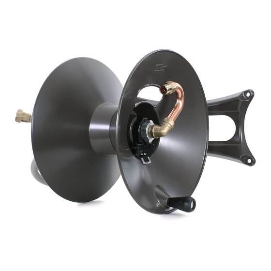
- Page 1 Wall Mount Garden Hose Reel Model 1041 Assembly & Installation Instructions...
-
Page 2: Questions? Problems
CONTENTS QUESTIONS? PROBLEMS? Please DO NOT contact or return this item to the retailer. Seek assistance directly from ELEY Corporation using the information below. PHONE: 1-866-523-2363 (toll free) MON- FRI, 8am to 5pm (CST) E-MAIL: support@eleyhosereels.com MON- FRI, 8am to 5pm (CST) - Page 3 Standard Reel IMPORTANT! If you purchased an Extra-Capacity Kit (Item# 1044) with your reel, please refer to the assembly instructions included with the Extra-Capacity Kit now. When Upgraded with you have completed those instructions, Extra-Capacity Kit then proceed to Step 3 of this manual. STEP 1 Place the Front Flange (4027) on...
- Page 4 STEP 2 Fasten flanges together using the three M6 x 20 Hex Socket Head Cap Screws (4006) and the small hex end of the Hex Key Wrench (4003). STEP 3 Remove the screw from the Handle Assembly (2654). STEP 4 Install Handle Assembly into Front Flange.
- Page 5 STEP 5 Remove the two M10 x 25 Hex Socket Head Cap Screws (4013) and 3/8” Flat Washers (2520) from the Garden Hose Reel Arm (3071). STEP 6 Determine which direction you want the reel to operate. Parallel Perpendicular STEP 7 Attach the Garden Hose Reel Arm (3071) securely to the Wall Mount Base (2558) using the two previously removed M10 x 25 Hex Socket Head Cap Screws (4013) and 3/8”...
- Page 6 Step 8 Locate the reel base within 5 feet of your faucet. Note: Be certain there are no other objects that may interfere with the proper operation of your reel. Parallel Perpendicular Installation Option A - Masonry Walls (For Option B, stud-wall installation, skip ahead to page 8) Step A9 Use a marker or pencil to mark the location of the four mounting holes on your wall.
- Page 7 Step A10 Use a 5/16 inch masonry bit (not included) and drill 1-1/2 inch deep holes at the 4 marked locations. Helpful hints: Measure and then mark the masonry bit with masking tape to ensure you drill at the proper depth.
- Page 8 Installation Option B - Stud Walls Step B9 Use a marker or pencil to mark the location of the four mounting holes on your wall. Note: Locate studs prior to drilling. The reel must be fastened to 2 studs. Parallel Perpendicular Step B10 Use a 1/8 inch drill bit (not included) and drill 1-1/2 inch deep holes at the four marked locations.
- Page 9 Step B11 If you are fastening to lap siding, use the four Standoffs (2510) between the Wall Mounting base and the siding. Fasten the base to the wall with the four 1/4 x 2-1/2 inch Hex Head Lag Screws (2319) and 1/4 inch Flat Washers (2331). Perpendicular Parallel Step B12...
- Page 10 Step 13 - Insert the externally threaded (male) end of the Inlet hose (1087) into the axle tube until it is accessible from the other side. Parallel Perpendicular Step 14 - Install the Flange Assembly onto the axle with the crank handle to the outside. Parallel Perpendicular Step 15 -...
- Page 11 Step 16 Attach the Swivel (2914) to the inlet hose. Parallel Perpendicular Step 17 - Attach the Swivel to the axle. Hand tighten firmly. Parallel Perpendicular Page 11...
- Page 12 Step 18 Position the Hose Strap (4045) 32 inches from the internally threaded (Female) end of your garden hose. Step 19 Position the Hose Strap (4045) so the grommets pass through the small slot in the flange. Page 12...
- Page 13 Step 20 Tighten the hose strap. The M6 x 65 Hex Socket Head Cap Screw (4009) will pass through the 1/4 inch Flat Washer (2331) and the two brass grommets on the hose strap and then thread into the cage nut on the reel flange assembly.
- Page 14 How to use the Cam-Lever Brake As you pull the hose from the reel, our innovative cam-lever brake will prevent the reel from “free-spinning”, unrolling more hose than you want. The brake can be turned ON and OFF with the flick of the lever. BRAKE ON Pulling the hose out.
- Page 15 How to adjust the Cam-Lever Brake 1. Place the cam-lever in the “ON” position. 2. Pull enough hose off the reel to test the amount of drag created by the Cam-Lever Brake. a. Too little drag, and the reel will continue to unspool hose after you’ve stop pulling. i.
-
Page 16: Year Warranty
10 years(120 months). Warranty period starts from original invoice date. In the event of a defect or component failure, Eley Corporation will replace the specific component(s) free of charge.
Need help?
Do you have a question about the 1041 and is the answer not in the manual?
Questions and answers
I am going to buy the standard parallel hose reel and need to know how far off the wall the unit is from the wall to the furthest distance off the wall the unit is.