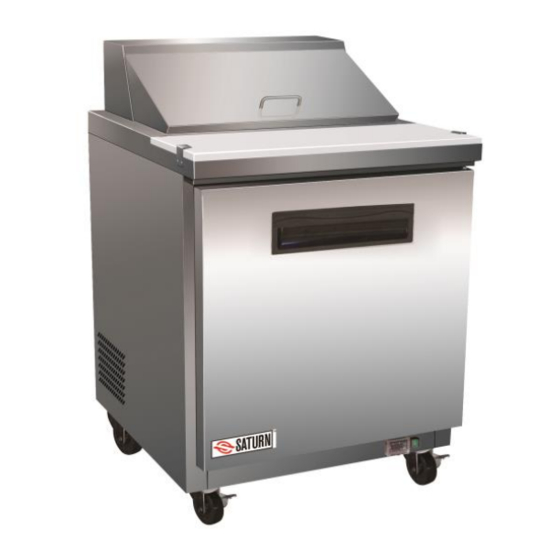
Summary of Contents for Saturn PSU28-8
- Page 1 Commercial Refrigerator Service Manual SANDWICH/SALAD PREP TABLE PSU28-8 Please read this manual completely before attempting to install or operate this equipment...
-
Page 2: Table Of Contents
TABLE OF CONTENTS 1. FEATURE CHART 1-1. OUTSIDE DRAWING AND MEASUREMENT FOR PSU28-8 2. WIRING DIAGRAM 2-1. REFRIGERATOR: PSU28-8 3. PARTS DETAILS 3-1. BOTTOM PANEL 3-2. REFRIGERATION COMPARTMENT 3-4. DOOR 3-5. COOLING COMPARTMENT 4. MAIN COMPONENTS 4-1. COMPRESSOR 4-2. COMPRESSOR RELAY 4-3. -
Page 3: Feature Chart
1. FEATURE CHART 1-1. OUTSIDE DRAWING OF PSU28-8... -
Page 4: Wiring Diagram
2. WIRING DIAGRAM 2-1. PSU28-8... -
Page 5: Parts Details
3. PARTS DETAILS 3-1. BOTTOM PANEL THERMOSTAT MAIN SWITCH... -
Page 6: Refrigeration Compartment
3-2. REFRIGERATION COMPARTMENT CYCLE ASSEMBLY CONDENSER FILTER DRIER CONDENSER FAN MOTOR WATER PAN COMPRESSOR... - Page 7 DRAIN PAN CONDENSER FAN MOTOR ASSEMBLY FAN COVER CONDENSER FAN MOTOR BLADE CONDENSER FAN MOTOR...
-
Page 8: Door
3-3. DOOR GASKET Magnetic gasket can be replaced without any tools. -
Page 9: Main Components
4. MAIN COMPONENTS 4-1. COMPRESSOR MODEL PSU28-8 R-134a Refrigerant Voltage 115V/60Hz Comp. NE2121Z Model Part code 27R.33 4-2. COMPRESSOR RELAY PSU28-8 Voltage 115V / 60Hz Relay Model 4-3. CONDENSER DRYER MODEL PSU28-8 Refrigerant R-134a Spec. XH-9 25g Part code GN1410TN.14 4-4. -
Page 10: Evaporator Fan Motor
4-5. EVAPORATOR FAN MOTOR MODEL PSU28-8 115V / 60Hz Voltage Motor 1238 Model Part code TUC27.31 4-6. CONDENSER FAN MOTOR MODEL PSU28-8 115V / 60Hz Voltage Motor BD03-04/C06 Model Part code 54F.09 4-7. EVAPORATOR DEFROST HEATER MODEL PSU28-8 Voltage 115V / 60Hz Spec. -
Page 11: Thermostat
5. ELECTRONIC CONTROLLER INSTRUCTION 5-1-1. DIXELL XR20C PARAMETER FOR REFRIGERATOR PSU28-8 Label Name Range Hidden Defa ℃ ℉ Par. ℃/℉ Set point LS-US -5/23 Differential 2/35. 0.1-25.5℃/1- 255℉ Minimum set point -50/- -50℃-SET/- 58℉-SET Maximum set point SET- 110/ 110℃/SET- 230℉... - Page 12 Resolution in=integer; dec .point Probe displayed P1;P2 Defrost termination Pb=by setting temperature; nP=by time Defrost termination 8/46. -50-50℃/-58- temperature 122℉ Interval between defrost 1-120ore cycles (Maximum) length 0-255min defrost Display during defrost rt, it, Set, DEF MAX display delay after 0-255min defrost Defrost delay after fast...
- Page 13 switchdEF=d efrost; =disabled; Htr=Cooling- heating Digital input alarm delay 0-255min Number of activation of 0-15 pressure no,Fan= normal; CPr= Compressor status with comp.OFF; open door F-C= Compr.OFF & fan.OFF Kind of probe Ptc;ntc ntc/ Room probe display Evaporator probe display Software release Map code 5-1-2.
- Page 14 1.1 Function of LEDS 2. MAIN FUNCTIONS 2.1 HOW TO VIEW THE SET POINT 1. Push and immediately release the SET key: the display will show the set point value. 2. Push and immediately release the SET key or wait for 5 seconds to display the sensor value again.
-
Page 15: Replacement Of Main Components
6. REPLACEMENT OF MAIN COMPONENTS 6-1. BOTTOM PANEL PARTS 6-1-1. UNSCREW BOTH SIDES OF THE BOTTOM PANEL 6-1-2. PULL THE BOTTOM PANEL OUT... -
Page 16: Door Changing
6-1-3. UNSCREW THE JUNCTION BOX 6-2. DOOR CHANGING 6-2-1. UNSCREW THE BOTTOM HINGE... - Page 17 6-2-2. PULL DOWN DOOR 6-2-3. CHANGE THE DOOR HINGE. A. PUT THE DOOR ON A FLAT LEVEL B. UNSCREW THE HINGE...
-
Page 18: Refrigeration Compartment Parts
C. PULL OUT THE SPRING HINGE 6-3. REFRIGERATION COMPARTMENT PARTS 6-3-1. BEFORE OPENING THE REFRIGERATION COMPARTMENT, PLEASE TAKE ALL THE PANS OUT AND TAKE THE PAN SUPPORT OFF 6-3-2. TAKE THE SHELVES, K SHAPE CLIPS AND SENSOR OFF... - Page 19 6-3-3. UNSCREW THE EVAPORATOR COVER 6-3-4. TAKE OFF THE EVAPORATOR COVER 6-3-5. CHANGE EVAPORATOR AND WATER PAN A. UNSCREW THE EVAPORATOR...
-
Page 20: Condensing Unit
B. BEFORE CHANGING THE EVAPORATOR, CUT OFF THE EVAPORATOR PIPE AND DISCONNECT THE WIRE TO THE SENSOR C. UNSCREW THE SCREWS FOUND AT THE TOP OF THE EVAPORATOR, AND DISCONNECT IT. REPLACE THE EVAPORATOR AND REATTACH THE PIPE AND CONNECT THE SENSOR WIRES 6-4. - Page 21 6-4-2. UNSCREW THE UNIT BOARD. YOU CAN PULL THE UNIT BOARD OUT FOR ANY REPAIRS OR CLEANING...
- Page 22 CAUTION: BE CAREFUL OF ELECTRIC SHOCK. CAUTION: MAKE SURE THE POWER SUPPLY IS CUT OFF BEFORE ANY SERVICE IS PERFORMED. CAUTION: CONDENSING UNIT MAY BE VERY HOT. BE SURE IT IS COOL BEFORE ANY SERVICE IS PERFORMED.


Need help?
Do you have a question about the PSU28-8 and is the answer not in the manual?
Questions and answers