Advertisement
Available languages
Available languages
Use & Care Guide
Manual de Uso y Cuidado
English/Español
Kenmore
®
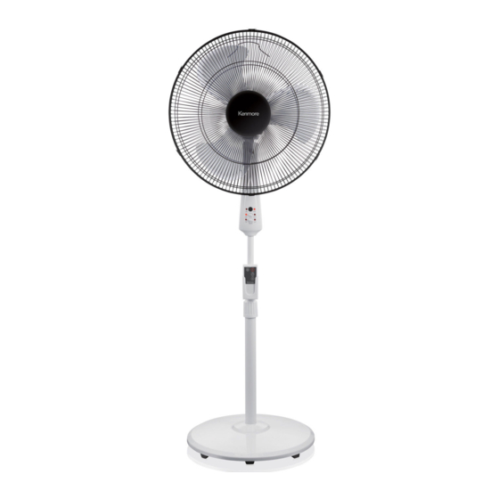
18" Stand Fan with
Remote Control
3 Speeds, Oscillating Action, Adjustable Tilt
Ventilador de Pedestal con
Control Remoto 18"
3 Velocidades, Acción Oscilante, Inclinación Ajustable
Model/Modelo: 405.35182510
Customer Assistance /Asistencia al Cliente
1-866-646-4332
Sears Brands Management Corporation
Hoffman Estates, IL 60179 U.S.A.
www.kenmore.com
www.sears.com
www.kmart.com
®
Advertisement
Table of Contents

Related Manuals for Kenmore 405.35182510


Summary of Contents for Kenmore 405.35182510
- Page 1 18" Stand Fan with Remote Control 3 Speeds, Oscillating Action, Adjustable Tilt Ventilador de Pedestal con Control Remoto 18" 3 Velocidades, Acción Oscilante, Inclinación Ajustable Model/Modelo: 405.35182510 Customer Assistance /Asistencia al Cliente 1-866-646-4332 Sears Brands Management Corporation Hoffman Estates, IL 60179 U.S.A. www.kenmore.com www.sears.com...
-
Page 2: Rules For Safe Operation
READ AND SAVE THESE INSTRUCTIONS CAUTION Read and follow all instructions before operating fan. Do not use fan if any part are damaged or missing. WARNING 1. This appliance is not intended for use by young children or infirm persons without supervision. - Page 3 PART FIGURE 1.Front guard 2.Spinner 3.Blade set 4.Plastic nut 5.Rear guard 6.Motor unit 7. Oscillation Control Button 8.Fan neck 9.Control panel 12.Remote Control Holder 10. Height adjustment ring 13. Floor Base 11.Remote Control 14. Finger Screw ASSEMBLY OF BASE 1. Unscrew the Finger screw and washer from the bottom of the Extension pole. Fig.
- Page 4 GUARD & FAN BLADE ASSEMBLY 1. Unscrew and remove the spinner clockwise (or remove from parts bag) and the plastic nut counterclockwise. Fig. 6. Mount the rear guard against the motor face so that the pin at the motor face bottom fits through the tear drop hole in the rear guard mounting ring.
-
Page 5: Battery Installation
“ ” MODE KEY Press this key to change speed from Normal to Natural mode. In Natural mode, the fan speed cycles from top speed to slower speed in each fan speed setting. When in Natural mode, the fan speed indicator on the control panel will flash on and off. Press this key again to resume Normal speed. -
Page 6: Battery Instructions
BATTERY INSTRUCTIONS - Do not dispose of batteries in fire; batteries may explode or leak. - Do not mix old and new batteries. Replace all batteries at the same time. - Do not mix alkaline, standard and rechargeable batteries together in the battery compartment. Use only one battery type. HOW TO USING THE REMOTE CONTROLLER CORRECTLY Point the remote control at the receptor (black circle) on the fan control panel. -
Page 7: Fuse Replacement
FUSE REPLACEMENT 1. Grasp the plug and remove it from the receptacle or other outlet device. Do not unplug by pulling on the cord. 2. Open the fuse cover. Slide open the fuse access cover on top of attachment plug towards blades. 3. - Page 8 LEA Y GUARDE ESTAS INSTRUCCIONES PRECAUCIÓN Lea y siga todas las instrucciones antes de operar el ventilador. No lo utilice si alguna pieza está dañada o pérdida. ADVERTENCIA 1. Este aparato no está diseñado para uso por los niños pequeños o personas enfermas sin supervisión.
- Page 9 (2) No opere ningún ventilador con un cable o enchufe dañado. Descarte el ventilador o llame al Servicio de Atención al Cliente al 1-866-646-4332 para hacer arreglos para la posible reparación. (3) No haga funcionar el cable bajo la alfombra. No cubra el cable con alfombrillas, tapetes, o cubiertas similares.
-
Page 10: Montaje De La Base
FIGURA DE PIEZAS 1. Guarda frontal 2. Cono de rectificación 3. Conjunto de pala 4. Tuerca de plástico 5. Guarda trasera 6. Unidad de motor 7. Botón de control de oscilación 8. Cuello del ventilador 9. Panel de control 10. Anillo de ajuste de altura 11. - Page 11 Fig.1 Fig.2 Fig.3 Fig.4 Orificio de montaje Aflojar MONTAJE DE LA PALA Y REJILLA 1. Desatornille y retire el cono de rectificación a derecha (u obténgalo desde la bolsa de piezas) y la tuerca de plástico a izquierda (Figura 6). Debería sostener el eje en su lugar con una mano para desatornillar el cono de rectificación con la otra mano.
-
Page 12: Instrucciones De Operación
INSTRUCCIONES DE OPERACIÓN I. Control Remoto (Figura 9) “ ” TECLA ENCENDIDO/APAGADO Pulse esta tecla para encender el ventilador. El ventilador reiniciará a funcionar con la configuración de velocidad y modo anterior. Pulse esta tecla de nuevo para apagar el ventilador. “... -
Page 13: Instalación De Pilas
IV. Ajuste de Altura del Ventilador Botón de control de oscilación Afloje el Anillo de ajuste de altura en la parte superior del poste de extensión. Levante o baje el poste interno metálico a la altura deseada y apriete el anillo de ajuste de altura apretadamente. - Page 14 MOTOR OVERHEAT PROTECTION El motor cuenta con un fusible térmico que se funde para apagar el ventilador si el motor del ventilador se vuelve muy calentado. El apagado permite que el motor se refrigere antes de que las piezas de plástico del ventilador se deformen por el alto calor.
-
Page 15: Reemplazo Del Fusible
REEMPLAZO DEL FUSIBLE 1. Tome el enchufe y retírelo desde el tomacorriente u otro aparato de salida. No lo desenchufe tirando el cable. 2. Abra la cubierta de fusibles. Deslice para abrir la cubierta de acceso a fusibles en la parte superior del enchufe hacia las palas. 3. - Page 16 WITH PROOF OF SALE, a defective appliance will be replaced free of charge. For warranty coverage details to obtain free replacement, visit the web page: www. kenmore. com/ warranty This warranty is void if this appliance is ever used for other than private household purposes.
Need help?
Do you have a question about the 405.35182510 and is the answer not in the manual?
Questions and answers
Can I take the motor and fan from a non-remote Kenmore stand fan and replace the motor and fan from a Kenmore remote controlled stand fan? And will the remote control still work?